Fixing device and flexible sleeve used in the fixing device

a fixing device and flexible technology, applied in the field of fixing devices, can solve the problems of weakening the electric field intensity at the periphery of the fixing nip, prone to occur, and high material recording intensity, so as to prevent image defects, suppress the separation charging of the fixing sleeve, and achieve high-quality image formation

Inactive Publication Date: 2011-09-29
CANON KK
View PDF7 Cites 6 Cited by
  • Summary
  • Abstract
  • Description
  • Claims
  • Application Information

AI Technical Summary

Benefits of technology

[0012]A principal object of the present invention is to provide a fixing device capable of permitting high-quality image formation by suppressing separation charging of a sleeve while sufficiently retaining a constraint force of toner onto a recording material thereby to prevent image defects such as tailing and separation offset.

Problems solved by technology

However, when the resistance of the parting layer is excessively increased, image defect which is called “separation offset” by the present inventors such that separation discharge at the time when the recording material has passed through the fixing nip occurs in a large amount to electrostatically separate the unfixed toner image from a subsequent recording material.
This problem is liable to occur in a low humidity environment in which the recording material has a high resistance.
However, in this case, the resistance of the parting layer which is an outermost layer is lowered, thus weakening electric field intensity at the periphery of the fixing nip.

Method used


Image

  • Fixing device and flexible sleeve used in the fixing device
  • Fixing device and flexible sleeve used in the fixing device
  • Fixing device and flexible sleeve used in the fixing device

Examples


embodiment 1

Image Forming Apparatus

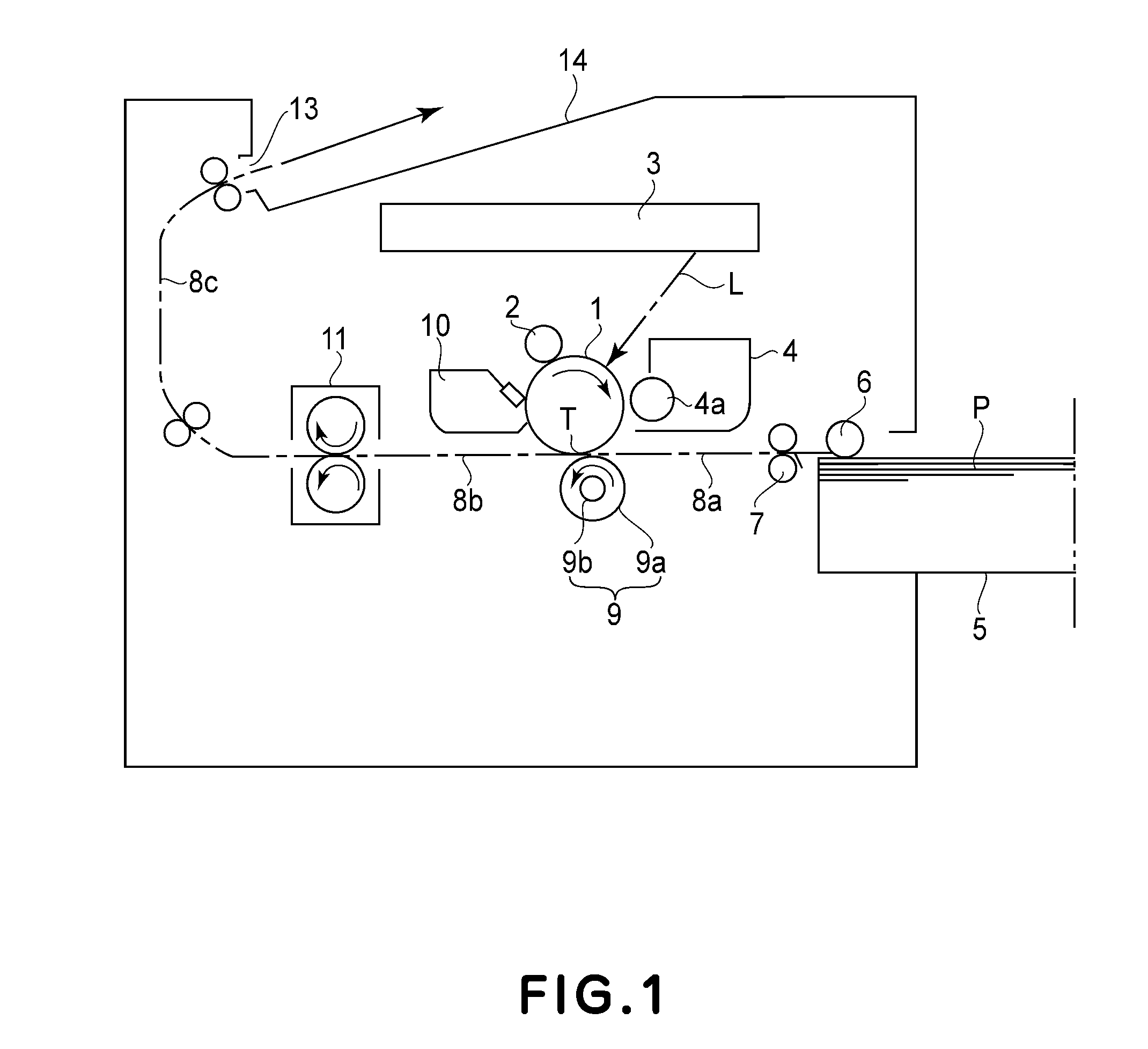
[0034]FIG. 1 is a schematic illustration of an image forming apparatus according to this embodiment. The image forming apparatus in this embodiment is a laser beam printer utilizing a transfer type electrophotographic process. In this embodiment, the image forming apparatus capable of forming an image only on one side is used as an example.

[0035]An electrophotographic photosensitive drum 1 as an image bearing member is rotationally driven in the clockwise direction indicated by an arrow at a predetermined peripheral speed (process speed).

[0036]A contact charging roller 2 electrically charges the surface of the photosensitive drum 1 uniformly to a predetermined polarity and a predetermined potential (primary charging). In this embodiment, a voltage of −600 V is applied to the charging roller 2, so that the photosensitive drum 1 is charged to a polarity and a potential which are substantially equivalent to those of the applied voltage.

[0037]A laser beam scanner ...


PUM


Abstract

A fixing device for fixing on a recording material a toner image formed on the recording material includes a flexible sleeve including a resinous base layer, a parting layer and an adhesive layer for bonding the base layer and the parting layer; a heater contacted to an inner surface of the sleeve; a pressing member for forming a nip, in which the recording material on which the toner image has been formed is nipped and conveyed, between itself and the sleeve to which the heater is contacted; a voltage applying member for applying a voltage, of a polarity identical to a polarity of toner; and a grounding member, contactable to the recording material in a nipped state in the nip, for grounding the recording material. In a thickness direction of the layers, an electric resistance of the adhesive layer is larger than that of the parting layer and the electric resistance of the parting layer is larger than that of the base layer. The voltage applying member applies the voltage to the sleeve in contact with the base layer.

Description

FIELD OF THE INVENTION AND RELATED ART[0001]The present invention relates to a fixing device, for fixing a toner image, for use with an image forming apparatus such as a copying machine, a laser beam printer, a facsimile machine or a multi-function machine having a combination of functions of these machines.[0002]In the image forming apparatus, as the fixing device for fixing the toner image on a recording material, a SURF-heating type fixing device has been used. This fixing device includes a heater, a stay which is a heater supporting member, a sleeve which is a heat-resistant film containing the heater and a pressing roller for forming a fixing nip between the pressing roller and the sleeve to which the heater is contacted. When the recording material is conveyed while being nipped in the fixing nip, heat of the heater is applied to the recording material, so that an unfixed toner image formed on the surface of the recording material is heat-fixed on the surface of the recording ...

Claims


Application Information

Patent Timeline
Patent Type & Authority Applications(United States)
IPC IPC(8): G03G15/20
CPCG03G2215/2035G03G15/2053
Inventor UCHIYAMA, KOJIUCHIYAMA, TAKAHIRONAKAHARA, HISASHI
Owner CANON KK
Why Eureka
Try Eureka