Workpiece transport method and workpiece transport device

a technology for workpieces and transport devices, applied in storage devices, gripping heads, thin material processing, etc., can solve problems such as damage to circuit surfaces, reduced processing speed, and complicated processing

Inactive Publication Date: 2011-09-29
NITTO DENKO CORP
View PDF1 Cites 12 Cited by
  • Summary
  • Abstract
  • Description
  • Claims
  • Application Information

AI Technical Summary

Benefits of technology

[0012]This invention has one object to provide a workpiece transport method and device for transport a workpiece accurately regardless of types of workpiece.

Problems solved by technology

Consequently, it is necessary to repeat joining and separating of the adhesive tape, which causes complicated processing.
As a result, such disadvantages may arise as an upsized apparatus configuration and a reduced processing speed.
In such case, the exposed circuit surface of the wafer may directly be pressed onto a metal holding table, or the wafer may slide in a rolling direction of the joining roller, which may cause damages in the circuit surface.
There arises a new problem that the sheet on the holding member for suction-holding has a reduced suction force, and the sheet cannot be suction-held and transported positively.
However, there arises a problem that the holding device cannot suspendingly hold and transport the wafer of a large diameter or a certain thickness having a large self-weight.

Method used


Image

  • Workpiece transport method and workpiece transport device
  • Workpiece transport method and workpiece transport device
  • Workpiece transport method and workpiece transport device

Examples


Embodiment Construction

[0044]One embodiment of the present invention is now described below with reference to the drawings.

[0045]In this embodiment, a case is to be described as one example where a workpiece transport device is provided with adhesive tape joining apparatus for manufacturing a mount frame by holding a rear face of a semiconductor wafer (hereinafter, simply referred to as a “wafer”) thinned through a back grinding process on a ring frame via an adhesive tape.

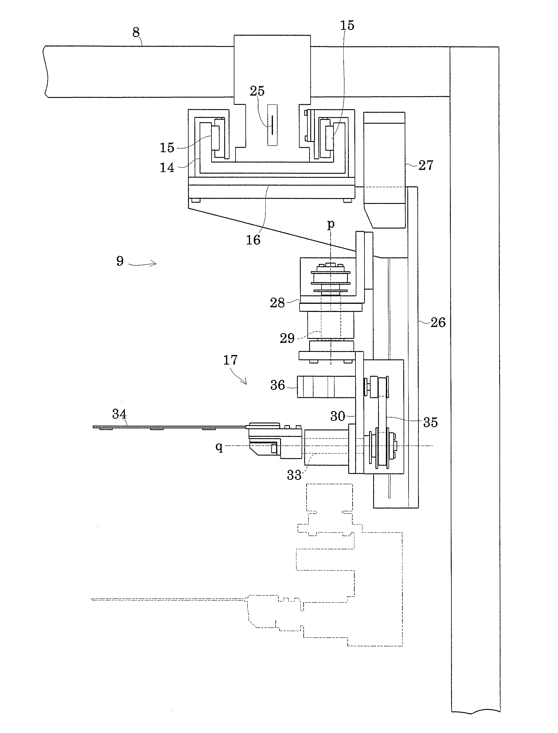
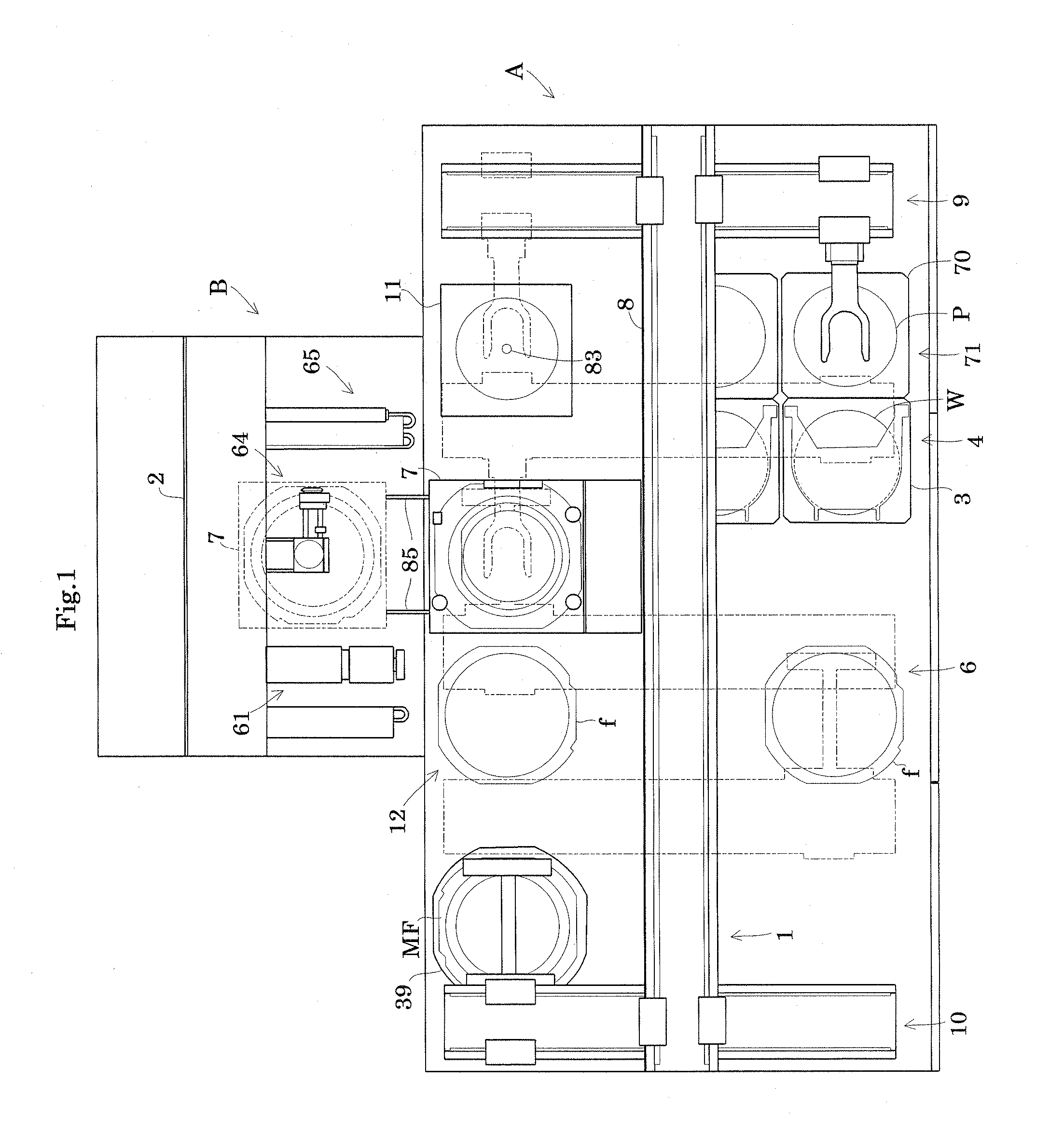
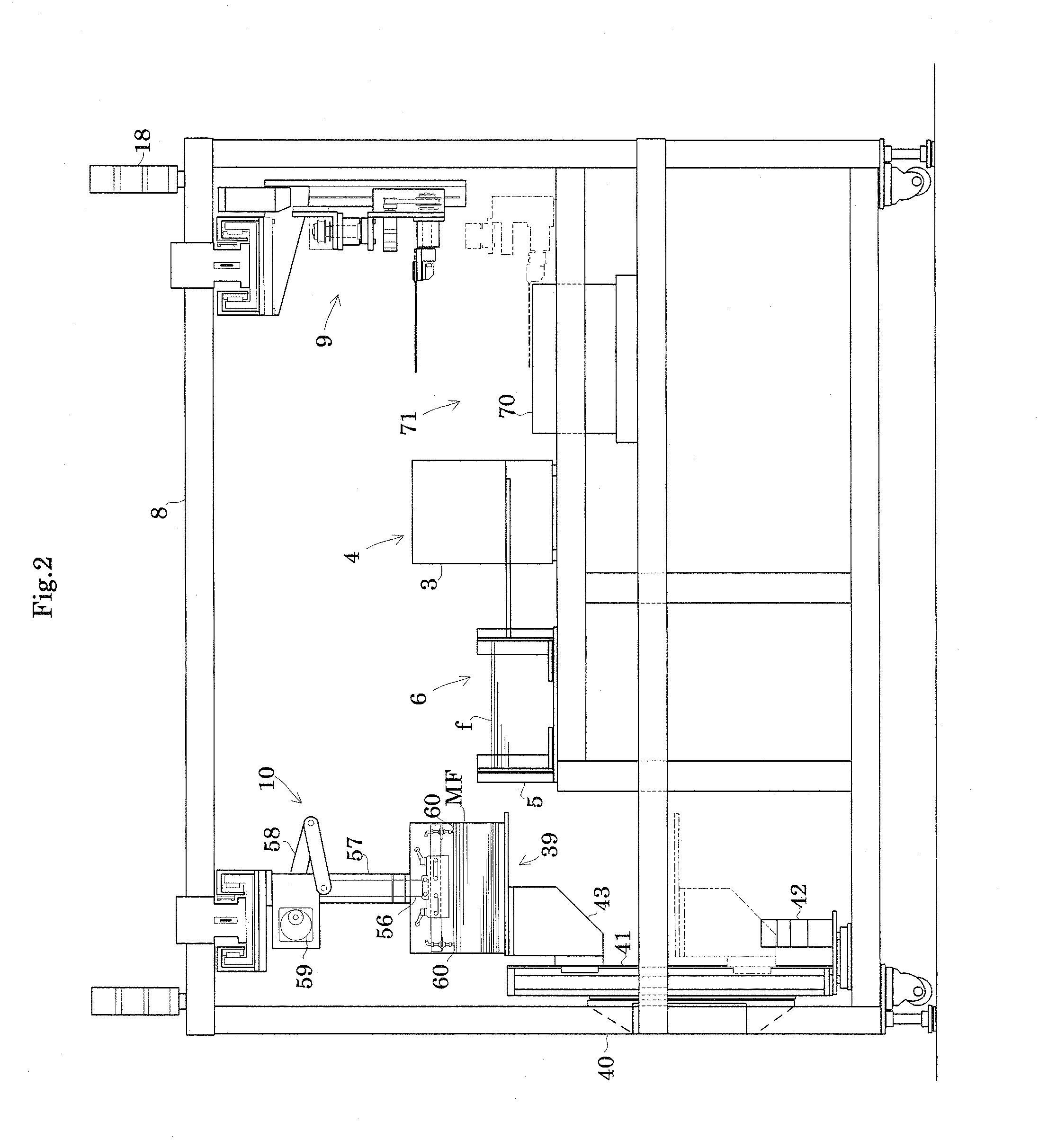
[0046]FIG. 1 is a plan view of adhesive tape joining apparatus. FIG. 2 is a front view thereof.

[0047]As shown in FIG. 1, the adhesive tape joining apparatus includes a laterally-extending rectangular section A and a protrusion section B connected at a center of the rectangular section A so as to protrude rearward from the center. Here, in the following description, a longitudinal direction of the rectangular section A is referred to as a horizontal direction. Moreover, a direction orthogonal to the horizontal direction is referred to as...


PUM


Abstract

Two or more pads having through holes formed therein concentrically at given pitches are provided on a U-shaped holding arm. Compressed air is sprayed from the pad to a protection sheet to generate negative pressure between a holding surface of the holding arm and the protection sheet for suspendingly holding a wafer with the protection sheet floating, or the pad suction-holds and transports a rear face of the wafer having an exposed circuit surface.

Description

BACKGROUND OF THE INVENTION[0001](1) Field of the Invention[0002]This invention relates to a workpiece transport method and device for transporting a workpiece including an electronic substrate such as a semiconductor wafer (hereinafter, appropriately referred to as a “wafer”) and a printed substrate, or a sheet, in a contact or non-contact manner in accordance with types of workpiece.[0003](2) Description of the Related Art[0004]A holder is known that transports while suspendingly holding a wafer as a substrate in a non-contact manner. The holder forms a chamber between upper and lower cases. Tow or more through holes are provided in a lower case side. Gases are sprayed from the through holes toward a wafer surface through supply of gases in the chamber. Specifically, spray of gases to the wafer surface leads to a region of negative pressure between the holder and the wafer to float and suspendingly hold the wafer due to a Bernoulli effect. See Japanese Patent Publication No. 2008-...

Claims


Application Information

Patent Timeline
Patent Type & Authority Applications(United States)
IPC IPC(8): B65G47/91
CPCH01L21/67092H01L21/6838H01L21/67132B25J15/0616B25J15/0683Y10S414/141
Inventor YAMAMOTO, MASAYUKIOKUNO, CHOUHEI
Owner NITTO DENKO CORP
Why Eureka
Try Eureka