Rotor Oscillation Preventing Structure and Steam Turbine Using the Same
a technology of preventing structure and preventing plate, which is applied in the direction of machines/engines, mechanical equipment, liquid fuel engines, etc., can solve the problems that the above-mentioned conventional art may not the whirl preventing plate cannot satisfactorily exhibit its own function, so as to reduce the occurrence potential of steam whirl, reduce the whirl velocity of leakage flow, and reduce the effect of absolute velocity
- Summary
- Abstract
- Description
- Claims
- Application Information
AI Technical Summary
Benefits of technology
Problems solved by technology
Method used
Image
Examples
embodiment 1
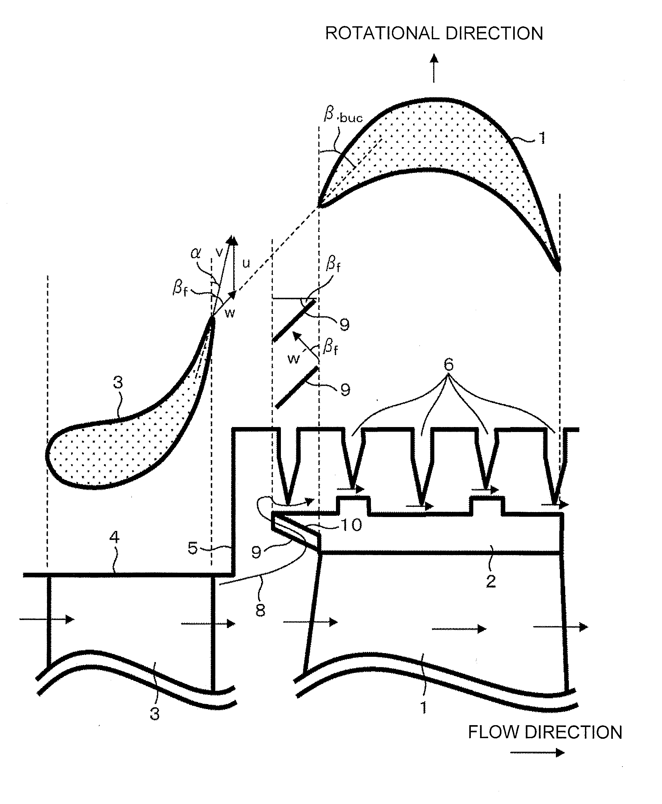
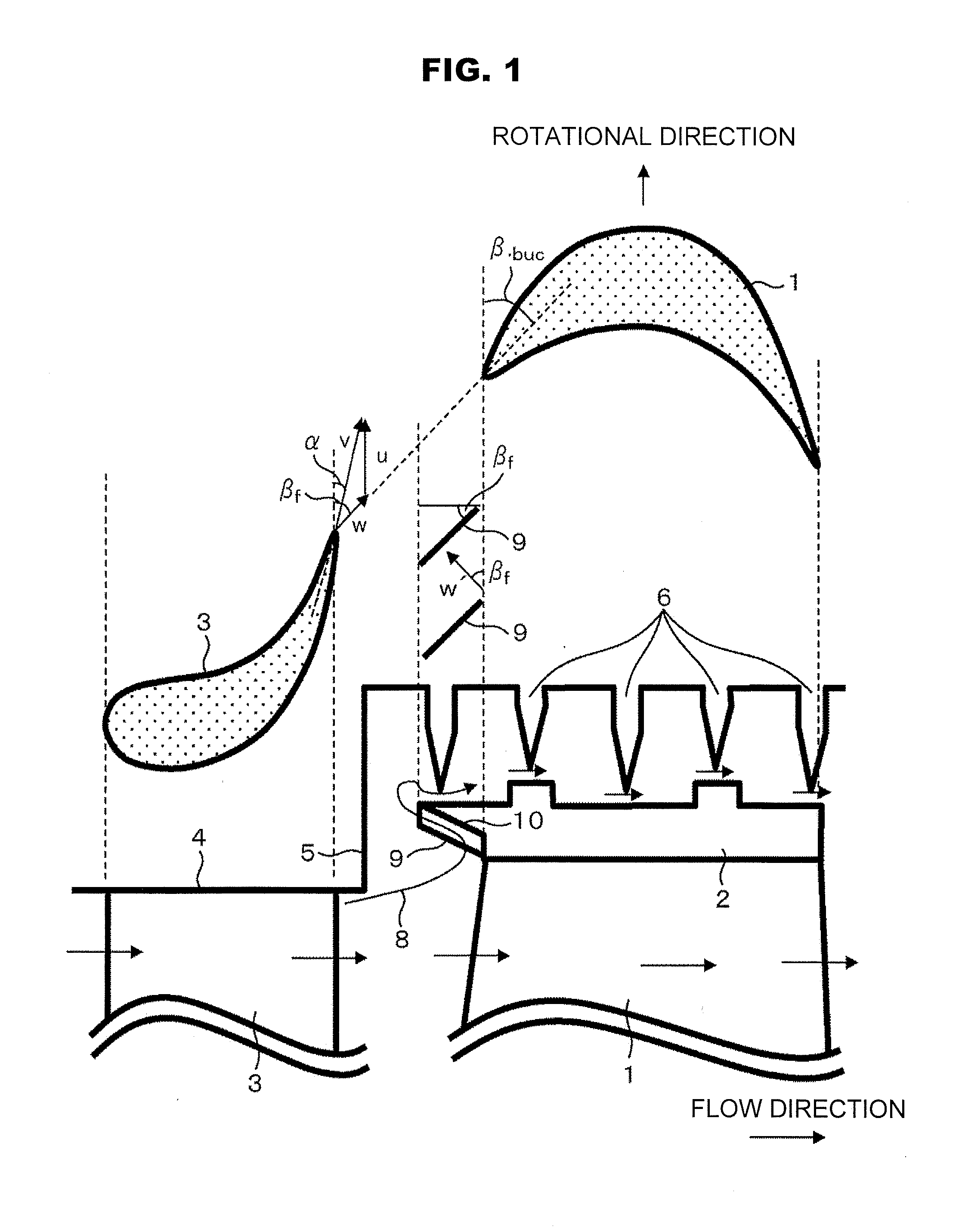
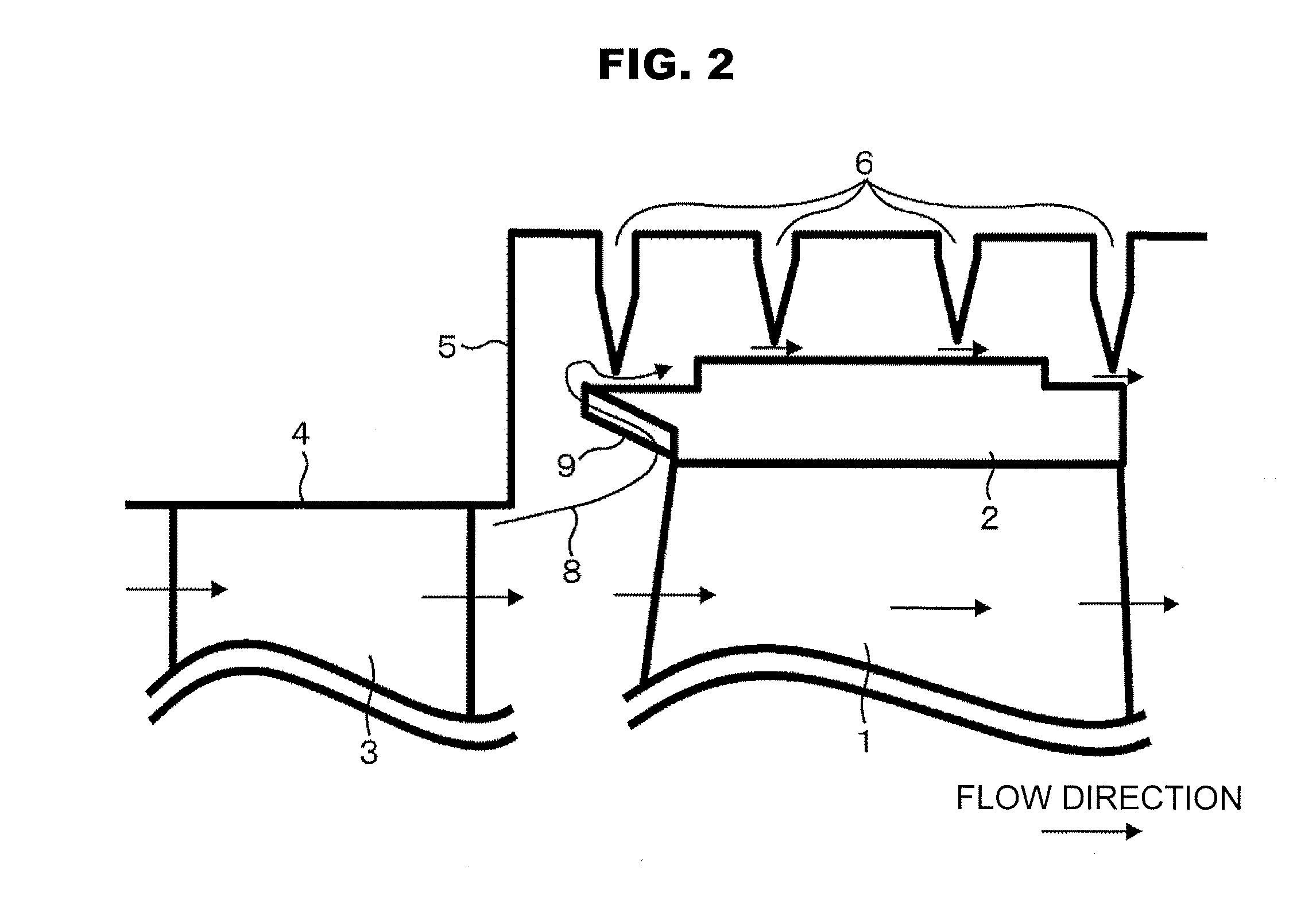
[0035]A first embodiment of the present invention will be described with reference to FIG. 1. FIG. 1 illustrates a structure of a turbine stage leakage portion as viewed from the radial direction (an upper view) and from the side (a lower view). In FIG. 1, there are shown a moving blade 1, a shroud cover 2, a stator vane 3, an outer circumferential side stationary wall 4, a vertical surface 5 of the outer circumferential side stationary wall, and labyrinth seal fins 6. In a steam turbine, the stator vanes 3 and the moving blades 1 are paired to form a turbine stage. A plurality of the stator vanes 3 are provided in the circumferential direction and their outer circumferential ends are supported by the outer circumferential side stationary wall 4 which is a stationary body. In contrast, a plurality of the moving blades 1 are secured to a turbine rotor not shown in the circumferential direction. The shroud cover 2 is provided on the outer circumferential side distal ends of the moving...
embodiment 2
[0045]A description is next given of a second embodiment of the present invention. FIG. 4 illustrates a structure of a turbine stage leakage portion as viewed from the side and FIG. 5 illustrates a structure of a whirl preventing groove 11 at a steam inlet side end portion of a shroud cover 2. Incidentally, constituent elements similar to those of the first embodiment are denoted with like reference numerals and their explanation is omitted.
[0046]The present embodiment differs from the first embodiment in that whirl preventing grooves 11 are characteristically provided at the steam inlet side end portion of the shroud cover 2 in place of the whirl preventing plate 9.
[0047]The whirl preventing grooves 11 radially passes through from the shroud cover inlet return portion 10 to the shroud outer circumferential surface. The whirl preventing grooves 11 as viewed from the axially upstream side are shown in FIG. 6A. The inner circumferential surface of the shroud cover return portion is ge...
PUM
 Abstract
Description
Claims
Application Information
 - R&D
- Intellectual Property
- Life Sciences
- Materials
- Tech Scout
- Unparalleled Data Quality
- Higher Quality Content
- 60% Fewer Hallucinations
Browse by: Latest US Patents, China's latest patents, Technical Efficacy Thesaurus, Application Domain, Technology Topic, Popular Technical Reports.
© 2025 PatSnap. All rights reserved.Legal|Privacy policy|Modern Slavery Act Transparency Statement|Sitemap|About US| Contact US: help@patsnap.com


