Internal combustion engine including valve deactivation mechanism

a technology of internal combustion engine and deactivation mechanism, which is applied in the direction of non-mechanical valves, electrical control, instruments, etc., can solve the problems of output power shock and response delay

Inactive Publication Date: 2011-10-06
HONDA MOTOR CO LTD
View PDF7 Cites 31 Cited by
  • Summary
  • Abstract
  • Description
  • Claims
  • Application Information

AI Technical Summary

Problems solved by technology

More particularly, in a cylinder deactivation engine including a valve deactivation mechanism, when the activation cylinder number is to be changed in response to an engine load, some interval of time is required after a driving instruction signal is outputted from an ECU to an oil control valve or the like until a hydraulic pressure necessary for the driving of a variable valve motion system is reached, and this provides a response delay.
If a cylinder deactivation / activation procedure does not take this response delay time into consideration, then an output power variation occurs when the activation cylinder number is changed, and there is a problem that an output power shock occurs.

Method used


Image

  • Internal combustion engine including valve deactivation mechanism
  • Internal combustion engine including valve deactivation mechanism
  • Internal combustion engine including valve deactivation mechanism

Examples


Embodiment Construction

[0038]In the following, an embodiment of the present invention is described with reference to the drawings.

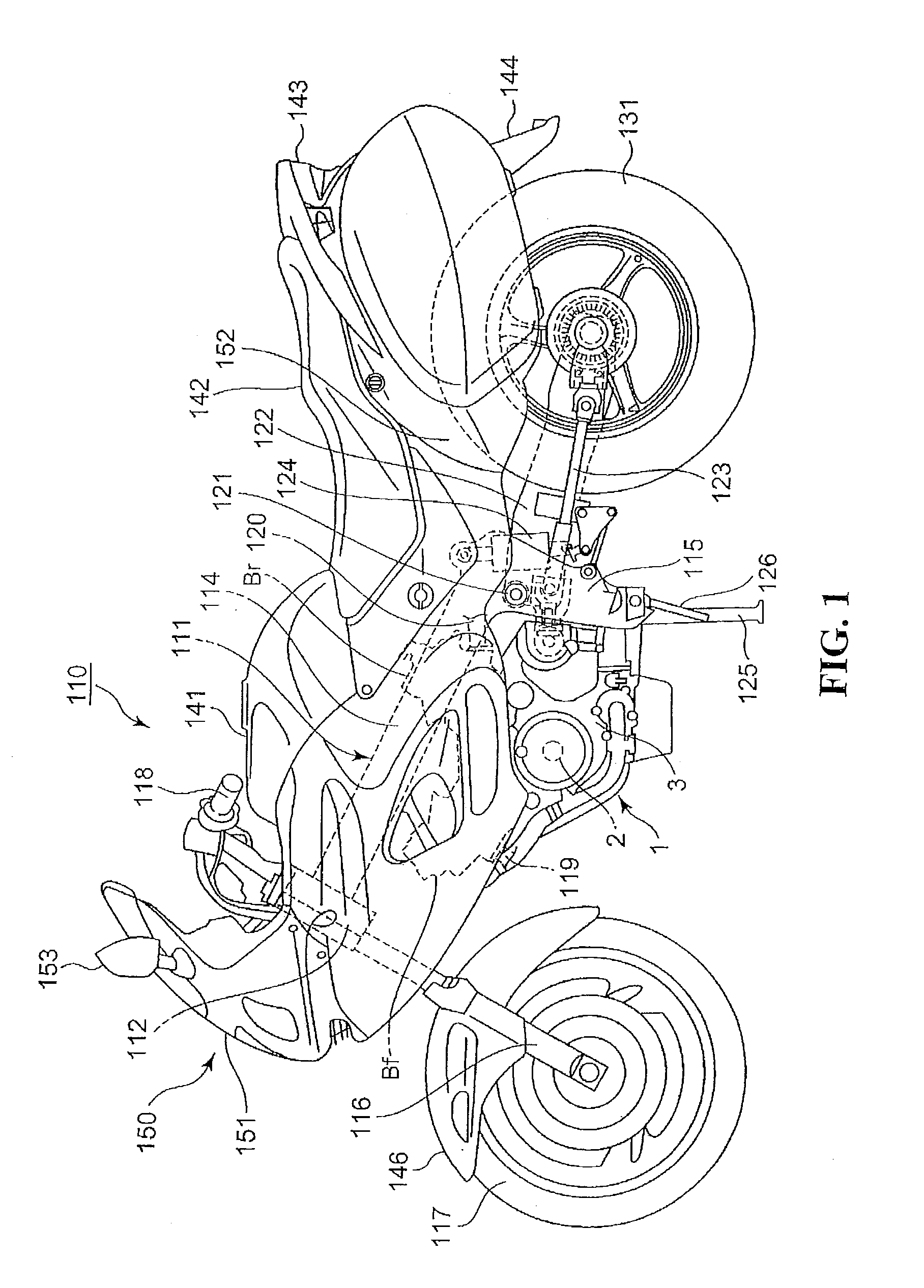
[0039]FIG. 1 is a left side elevational view showing a motorcycle which includes an internal combustion engine according to an embodiment of the present invention. It is to be noted that, in the following description, a term regarding a direction such as a forward, backward, leftward, rightward, upward or downward direction is used to represent a direction with reference to a vehicle body.

[0040]A vehicle body frame 111 of a motorcycle 110 includes a head pipe 112 positioned at a front portion of a vehicle body, a pair of left and right main frames 114 extending rearwardly from the head pipe 112 to the middle of the vehicle body, a pair of left and right pivot plates 115 extending downwardly from rear end portions of the main frames 114, and a rear frame (not shown) extending from rear end portions of the main frames 114 to a rear portion of the vehicle body.

[0041]A front fork 1...


PUM


Abstract

An internal combustion engine which includes a valve deactivation mechanism for reducing an output power shock upon changing of the cylinder number. In an internal combustion engine which includes a valve deactivation mechanism driven by a slide pin which is driven by hydraulic pressure, response delay time after a signal is sent to oil control valves until an intake valve and an exhaust valve are activated or deactivated is used to form a control map in response to control parameters, and the valve deactivation mechanism is controlled based on the control map.

Description

CROSS-REFERENCE TO RELATED APPLICATIONS[0001]The present application claims priority under 35 USC 119 to Japanese Patent Application No. 2010-083394 filed on Mar. 31, 2010 the entire contents of which are hereby incorporated by reference.BACKGROUND OF THE INVENTION[0002]1. Field of the Invention[0003]This invention relates to an internal combustion engine including a valve deactivation mechanism.[0004]2. Description of Background Art[0005]An internal combustion engine including a valve deactivation mechanism is conventionally known wherein the valve deactivation mechanism is driven by hydraulic pressure to control an intake valve and an exhaust valve of the internal combustion engine. See, for example, Japanese Patent Laid-Open No. Hei 9-256879.[0006]In addition, in an engine which uses a variable valve motion which uses hydraulic pressure, an oil control valve such as a spool valve is normally used in order to control the hydraulic pressure.[0007]More particularly, in a cylinder de...

Claims


Application Information

Patent Timeline
Patent Type & Authority Applications(United States)
IPC IPC(8): F02D28/00F01L9/02F02D1/18F02D43/00F01L9/10
CPCF01L1/181F01L1/25F01L13/0005F01L2105/00F02D13/06F02D37/02Y02T10/18F02D2041/0012F02D2200/023F01L9/02F02D13/02F02D17/02F02D41/0087F01L2305/00Y02T10/12F01L9/10
Inventor MAEHARA, HAYATOKITAWAKI, SHUNSUKESAITO, SHINJIASADA, YUKIHIRO
Owner HONDA MOTOR CO LTD
Why Eureka
Try Eureka