Vibration insulating device for a handheld work machine

a technology of vibration insulation and work machine, which is applied in the direction of metal sawing device, manufacturing tool, portable power-driven tools, etc., can solve the problems of difficult to remove and the removal of the supporting members from the coil spring requires a lot of time and effort, so as to facilitate the disassembly operation of the handheld work machine, easy to remove, and easy to remov

Inactive Publication Date: 2011-10-06
MAKITA CORP
View PDF2 Cites 10 Cited by
  • Summary
  • Abstract
  • Description
  • Claims
  • Application Information

AI Technical Summary

Benefits of technology

[0008]In this vibration insulating device, the general-purpose tightening tool can be engaged with the supporting members, and the supporting members can be removed easily from the coil spring by using the tightening tool. Moreover, even when the ends of the coil spring are firmly fixed to the supporting members, the supporting members can be easily removed from the coil spring by applying a large force to the supporting members using the tightening tool. It should be noted that the tightening tool can be used similarly when screwing the supporting members into the coil spring. Therefore, the vibration insulating device can be assembled easily.
[0009]According to the vibration insulating device described above, the supporting members can be easily removed from the coil spring by using a standard tightening tool. In addition, adopting this vibration insulating device facilitates the disassembly operation of the handheld work machine, allowing maintenance and repairs to be performed within a relatively short time.

Problems solved by technology

In so doing, a vibration insulating device also needs to be taken apart, but it is not easy to remove the supporting members from the coil spring as they are screwed into the coil spring.
In this case, removing the supporting members from the coil spring requires a lot of time and effort.

Method used


Image

  • Vibration insulating device for a handheld work machine
  • Vibration insulating device for a handheld work machine
  • Vibration insulating device for a handheld work machine

Examples


embodiment

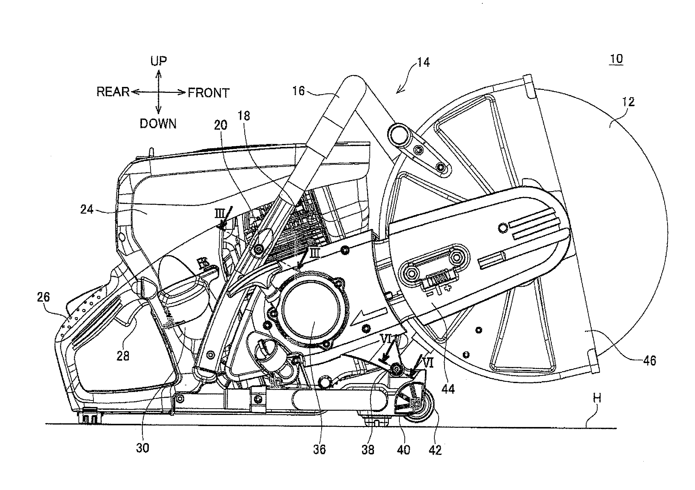
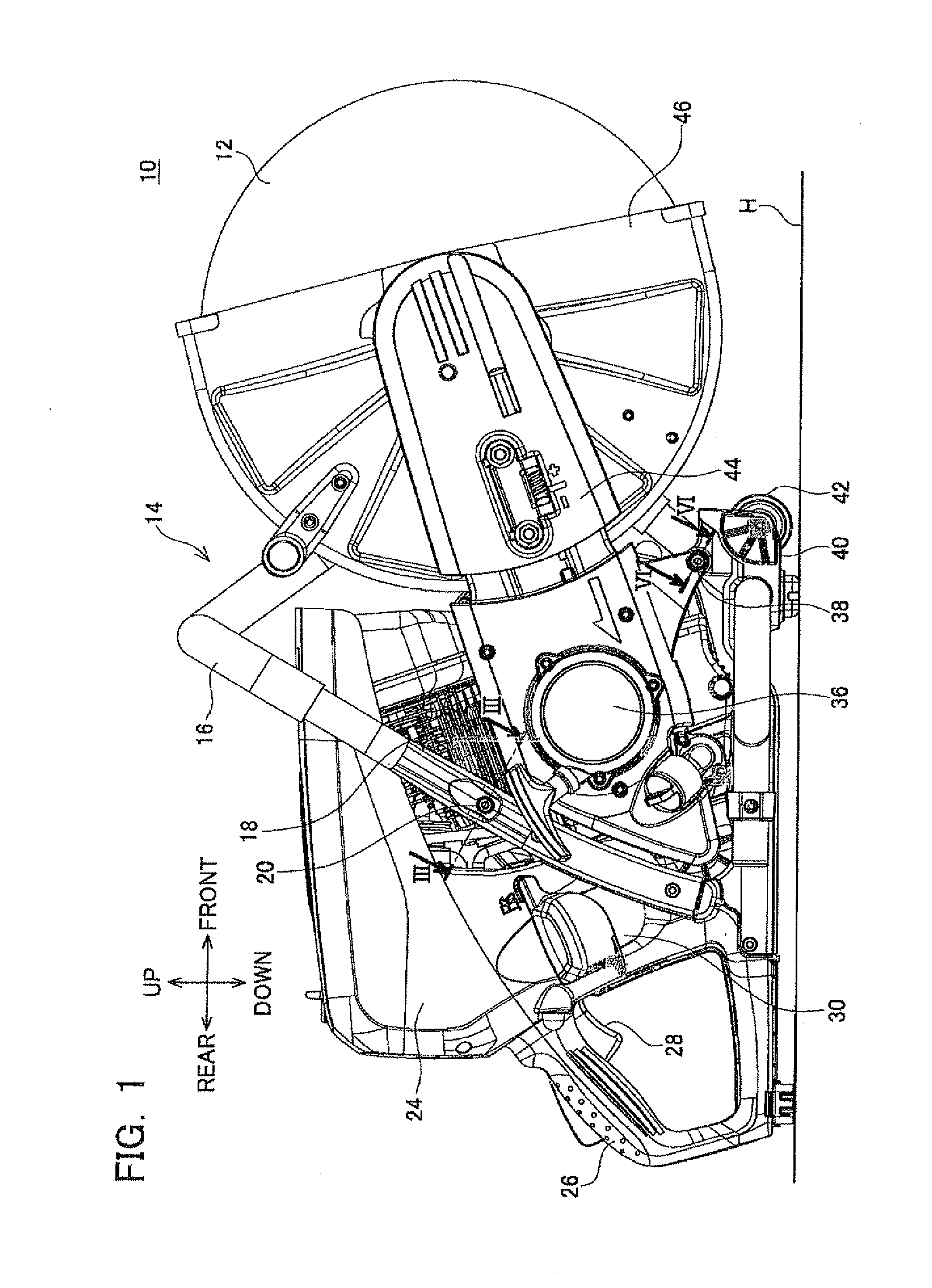
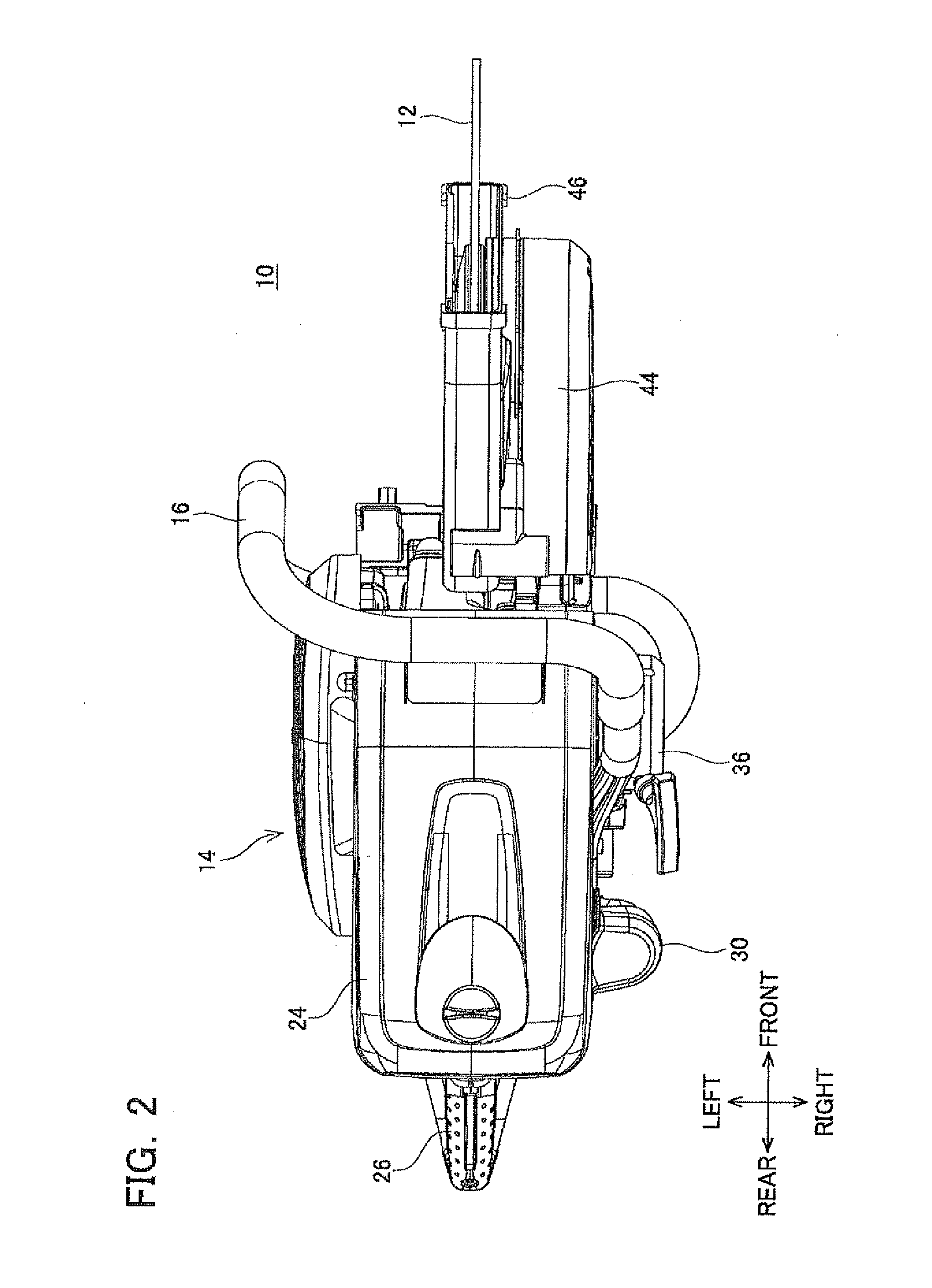
[0023]An engine-driven cutter, which is an embodiment of the present invention, is now described with reference to the drawings. FIG. 1 is a side view of an engine-driven cutter 10. FIG. 2 is a plan view of the engine-driven cutter 10. The engine-driven cutter 10 has a disk-shaped rotary blade 12, and a main body 14 for driving the rotary blade 12. The rotary blade 12 is capable of cutting lithic materials and metal materials. Therefore, the engine-driven cutter 10 is used for cutting concrete and steel frames at, e.g., a construction site.

[0024]As shown in FIGS. 1 and 2, when the engine-driven cutter 10 is placed on a horizontal plane H, the rotary blade 12 is located on one side in a horizontal direction relative to the main body 14. In the following explanation, on the basis of a state in which the engine-driven cutter 10 is placed on the horizontal plane H, the one side in the horizontal direction in which the rotary blade 12 is located relative to the main body 14 is referred t...


PUM

PropertyMeasurementUnit
shapeaaaaaaaaaa
timeaaaaaaaaaa
forceaaaaaaaaaa

Abstract

A vibration insulating device connects two members of a handheld work machine via a coil spring. One end of the coil spring is supported by a first supporting member fixed to one member, and the other end is supported by a second supporting member fixed to another member. At least one of the first and second supporting members includes a threaded groove that engages with the coil spring and a tool engaging portion that configured capable of being engaged with a general-purpose tightening tool.

Description

CROSS-REFERENCE TO RELATED APPLICATION(S)[0001]This application claims priority to Japanese Patent Application No. 2010-81578 filed on Mar. 31, 2010, the contents of which are hereby incorporated by reference into the present application.TECHNICAL FIELD[0002]The present application relates to a handheld work machine, and particularly to a vibration insulating device for the handheld work machine.DESCRIPTION OF RELATED ART[0003]Japanese Patent Application Publication No. 2001-116074 discloses a vibration insulating device for a handheld work machine. This vibration insulating device is arranged between two members of the handheld work machine. These two members are connected to each other by a coil spring. This type of vibration insulating device is arranged e.g. between a prime mover (e.g., an engine) and a grip grasped by a user, to prevent the transmission of vibrations from the prime mover to the user.[0004]The coil spring of the vibration insulating device is supported by a supp...

Claims


Application Information

Patent Timeline
Patent Type & Authority Applications(United States)
IPC IPC(8): B25F5/00
CPCB23D45/16F16F1/125B23D47/005
Inventor KONDO, MASAKIYAMAZAKI, SHINJI
Owner MAKITA CORP
Why Eureka
Try Eureka