Braking apparatus

a technology of braking apparatus and braking system, which is applied in the direction of braking system, braking components, transportation and packaging, etc., can solve the problems of high failure-safety requirements, and achieve the effect of low cos

Inactive Publication Date: 2011-10-06
TOYOTA JIDOSHA KK +1
View PDF0 Cites 43 Cited by
  • Summary
  • Abstract
  • Description
  • Claims
  • Application Information

AI Technical Summary

Benefits of technology

[0043]According to the present invention, even if part of the control unit in a braking apparatus breaks down, the fail-safe control thereof can be achieved surely and at a low cost.

Problems solved by technology

Accordingly, it is needed that the ECU always functions normally, and even if the CPU, etc., breaks down, high fail-safety is demanded.

Method used


Image

  • Braking apparatus
  • Braking apparatus
  • Braking apparatus

Examples


first embodiment

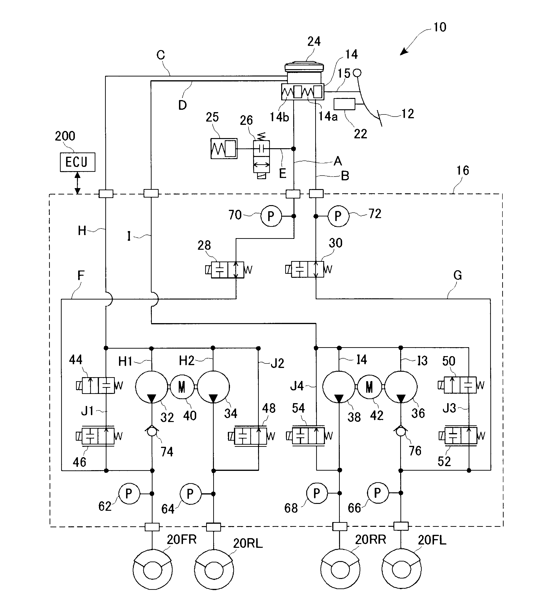
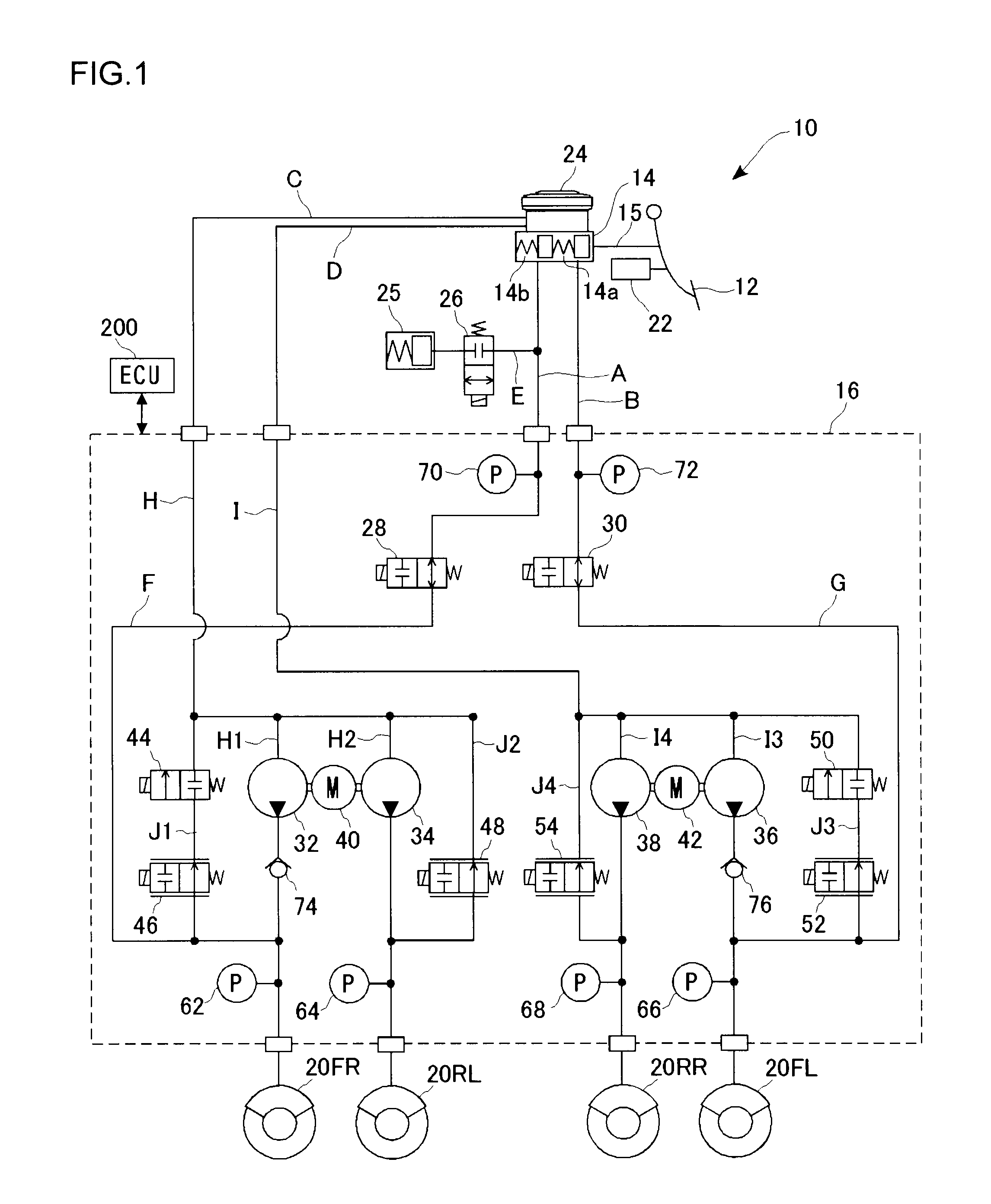
[0122]FIG. 1 is a systematic view illustrating a braking apparatus according to a first embodiment of the invention, centered on the fluid pressure circuit thereof. In the embodiment, a so-called X-shaped fluid pressure circuit including a system in which the right front wheel and the left rear wheel are connected and that in which the left front wheel and the right rear wheel are connected, is adopted.

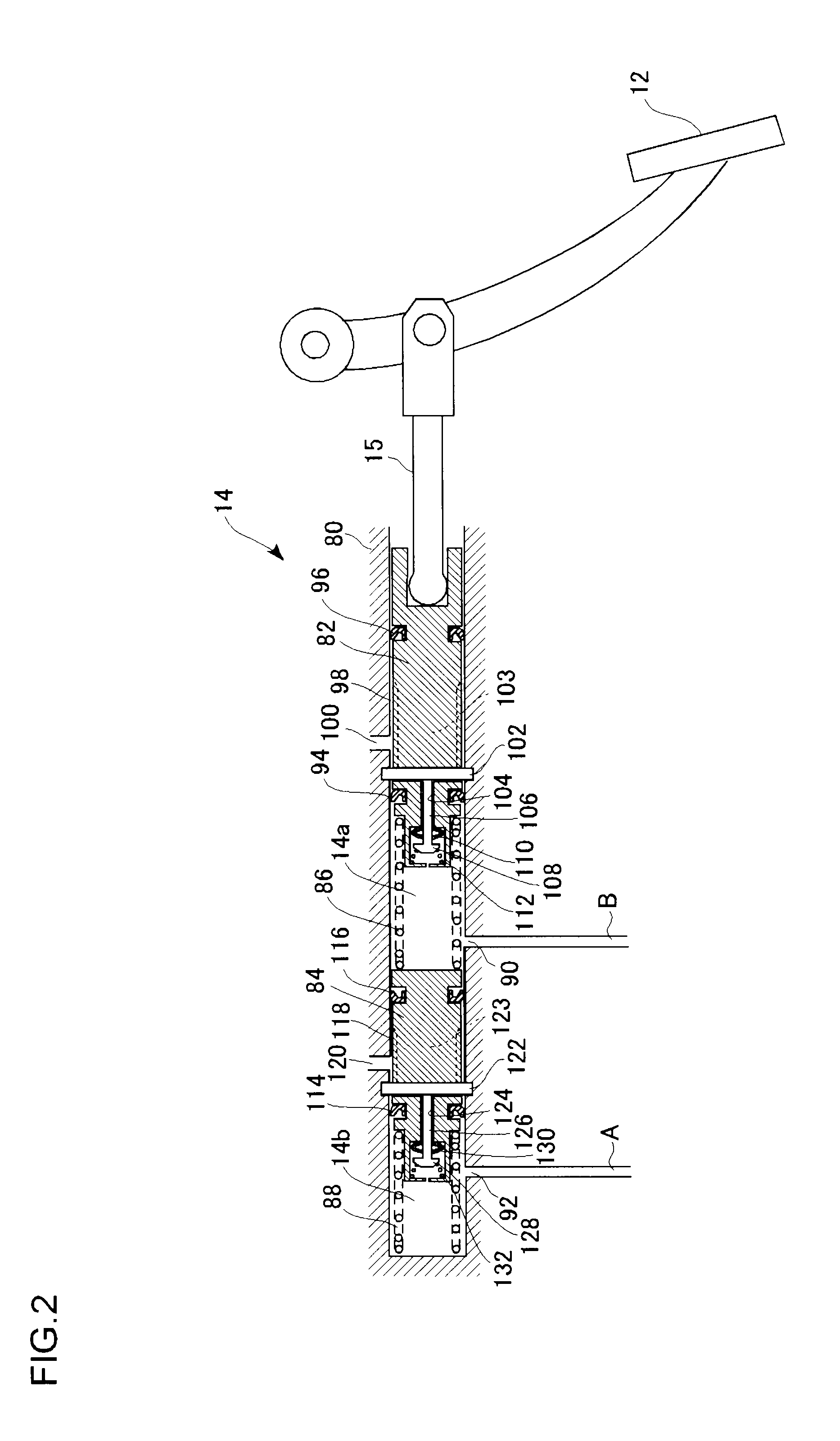
[0123]A braking apparatus 10 comprises a brake pedal 12, a master cylinder 14, a fluid pressure actuator 16, and wheel cylinders 20FL, 20FR, 20RL, and 20RR (hereinafter, sometimes collectively referred to as “wheel cylinder 20”). The braking apparatus 10 also comprises a brake ECU 200 as a control unit (braking control apparatus) for controlling the operation of each part thereof. The braking apparatus 10 provides braking force to each of the wheels by supplying, as an operating fluid, brake fluid to the wheel cylinder 20 and by controlling the fluid pressure (hereinafter, referred to...

second embodiment

[0177]Subsequently, a second embodiment according to the present invention will be described. The embodiment is almost the same as the first embodiment, except that an electrical booster is provided in the master cylinder. Accordingly, the configurations that are common with the first embodiment will be denoted with the same reference numerals and descriptions thereof will be omitted. FIG. 7 is a systematic view illustrating a braking apparatus according to the second embodiment, centered on the fluid pressure circuit thereof. FIG. 8 is a view exemplifying a motor driving method of an electrical booster in a fail state. The vertical axis of FIG. 8 represents the rotation speed of the motor and the horizontal axis thereof represents elapsed time.

[0178]As illustrated in FIG. 7, in a braking apparatus 210, an electrical booster 212 is provided in the master cylinder 14 such that the stepping-on of the brake pedal 12 can be assisted. The electrical booster 212 includes: a motor 214 that...

third embodiment

[0190]Subsequently, a third embodiment according to the present invention will be described. In the embodiment, the reservoir is built in the fluid pressure actuator, and the fail-safe control is executed by using the brake fluid retained in the built-in reservoir. FIG. 10 is a systematic view illustrating a braking apparatus according to the third embodiment, centered on the fluid pressure circuit thereof. In the embodiment, the same or like parts as in the first embodiment or the second embodiment are denoted with the same reference numerals, if necessary.

[0191]A braking apparatus 310 is configured as an apparatus in which the control for preventing lock of a wheel from occurring when a vehicle is rapidly braked or steered (ABS: Anti-lock Brake System) can be executed. The fluid pressure circuit in a fluid pressure actuator 316 is configured as a diagonal system in which the system for the right front wheel FR and the left rear wheel RL and the system for the left front wheel FL a...


PUM


Abstract

A braking apparatus according to an embodiment includes: a fluid pressure circuit that is provided between a master cylinder and a wheel cylinder, and that includes both a first system flow channel connecting a reservoir and at least one of the plurality of wheel cylinders, and a second system flow channel connecting at least one of the plurality of wheel cylinders and the master cylinder, and that forms a flow channel for supplying operating fluid to each of the wheel cylinders; and a pump provided in the first system flow channel and driven by the motor to increase the fluid pressure of the operating fluid to be supplied from the reservoir to the wheel cylinders. A control unit controls the driving state of the pump in order to drive, when a predetermined fail standard for braking control has been satisfied, the motor in accordance with the information detected by an operating state detection means, and executes fail-safe control for providing braking force by supplying the operating fluid discharged from the pump to the fluid pressure chamber in the master cylinder.

Description

TECHNICAL FIELD[0001]The present invention relates to braking control for controlling the braking force provided to a wheel of a vehicle.BACKGROUND TECHNOLOGY[0002]Conventionally, a braking apparatus has been known in which braking force is provided by generating, in a fluid pressure circuit, the fluid pressure in accordance with the operation amount of a brake pedal and by supplying the fluid pressure to the wheel cylinder in each of the wheels (see, for example, Patent Document 1). Various electromagnetic valves, such as pressure-increasing valve to be opened when fluid pressure is supplied, pressure-reducing valve to be opened when fluid pressure is released, and switch valve to be opened / closed when the supply channel of fluid pressure is switched, etc., are provided between a fluid pressure source and each of the wheel cylinders. The braking apparatus adjusts the supply / discharge amount of brake fluid to / from the wheel cylinder by controlling the opening / closing of these electr...

Claims


Application Information

Patent Timeline
Patent Type & Authority Applications(United States)
IPC IPC(8): B60T8/92B60T13/58B60T13/66B60T13/68B60T8/17
CPCB60T7/042B60T8/404B60T8/4081B60T8/4275B60T2270/413B60T8/885B60T8/94B60T13/166B60T13/686B60T8/4872
Inventor MIYAZAKI, TETSUYAYAMAMOTO, TAKAYUKIKOKUBO, KOICHIMASUDA, YOSHIO
Owner TOYOTA JIDOSHA KK
Why Eureka
Try Eureka