Hysteresis switch and electricity charging module using the same

a technology of electricity charging module and switch, which is applied in the direction of electronic switching, pulse technique, transportation and packaging, etc., can solve the problems of degrading charging efficiency, charging voltage, and insufficient charging of rechargeable batteries, and achieve stable charging voltage, increase the hysteresis characteristics, and the effect of increasing the turn-on voltage level

Active Publication Date: 2011-10-06
KOOKMIN UNIV IND ACAD COOP FOUND
View PDF2 Cites 180 Cited by
  • Summary
  • Abstract
  • Description
  • Claims
  • Application Information

AI Technical Summary

Benefits of technology

[0021]Since the electricity charging module of the present invention adopts electronic switches having larger hysteresis characteristics that has a higher turn-on voltage level than the turn-off voltage level, a stable charging voltage can be applied to the rechargeable ba

Problems solved by technology

Since the conventional battery charging module for charging rechargeable battery applies external power directly to the charging unit without using the storage capacitors, it may not sufficiently charge the rechargeable battery due to the lack of the charging current under energy harvesting environment.
Furthermore, if the supp

Method used


Image

  • Hysteresis switch and electricity charging module using the same
  • Hysteresis switch and electricity charging module using the same
  • Hysteresis switch and electricity charging module using the same

Examples


Embodiment Construction

[0027]Hereinafter, a preferred exemplary embodiment of a hysteresis switch and an electricity charging module using the same will be described in detail with reference to the attached drawings.

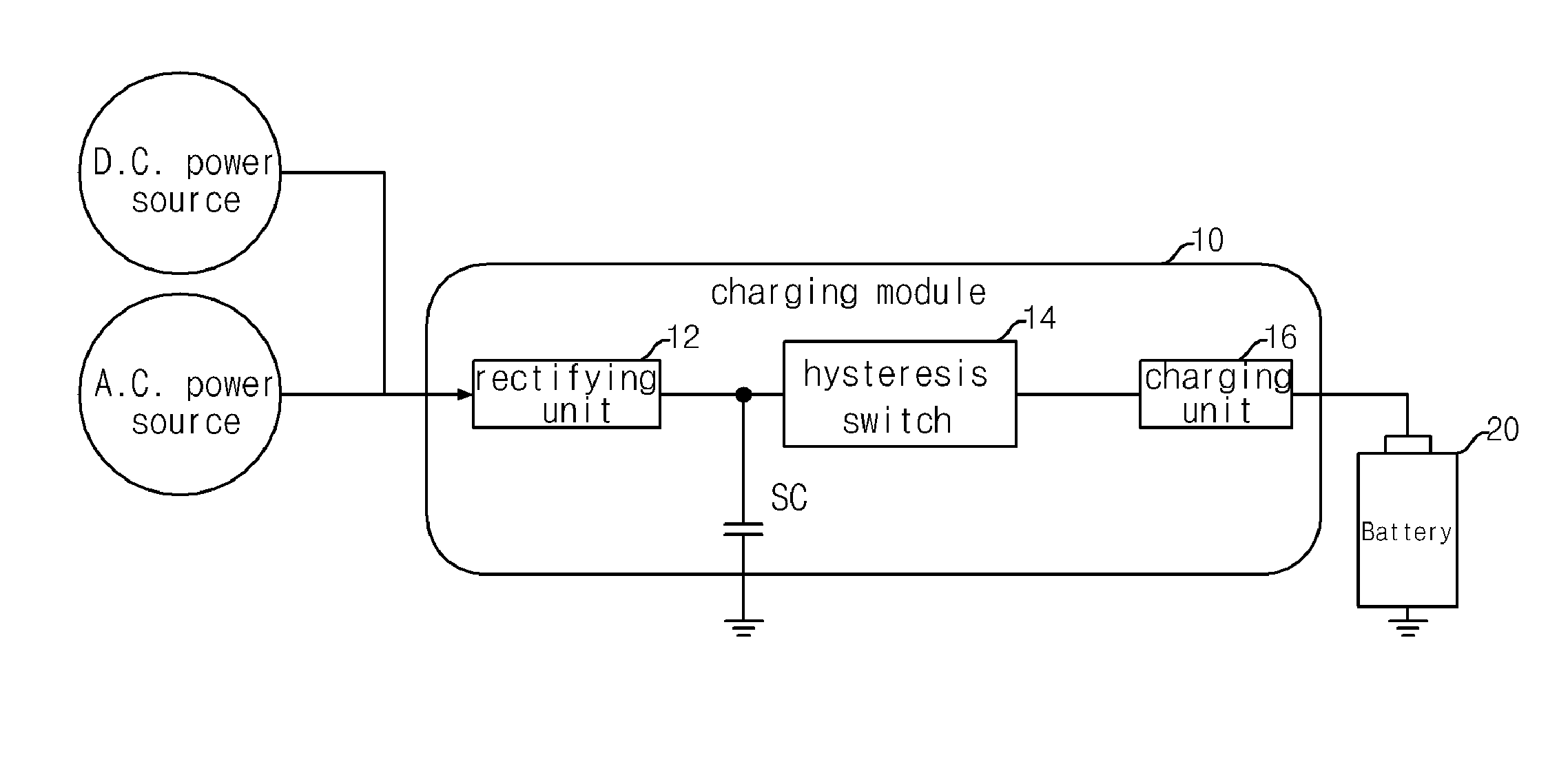
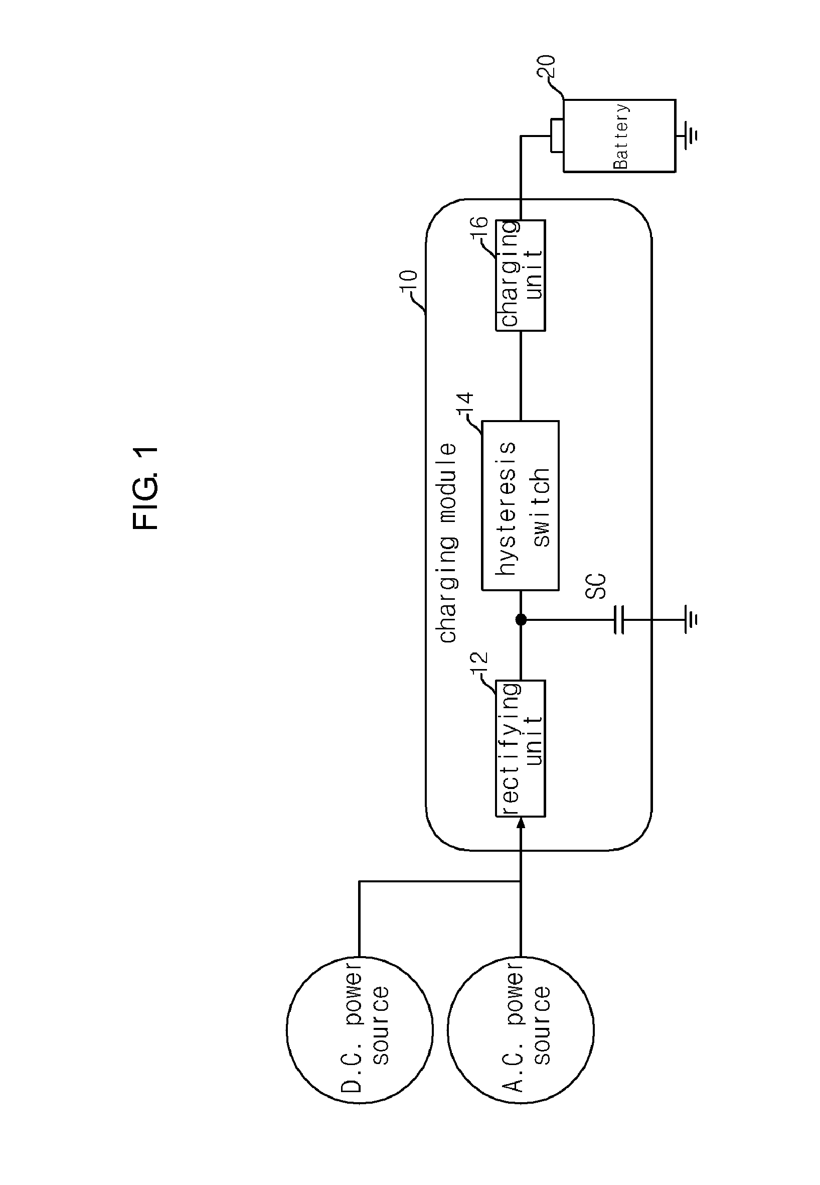
[0028]FIG. 1 is an electrical block diagram of an electricity charging module for a rechargeable battery adopting an electronic switch having hysteresis characteristics in accordance with the present invention. As illustrated in FIG. 1, an electronic switch having hysteresis characteristics 14 (hereinafter referred to as “hysteresis switch”) can be adopted by an electricity charging module 10 for charging a rechargeable battery 20; as an external power source for such electricity charging module 10, a D.C. power or an A.C. power can be applied.

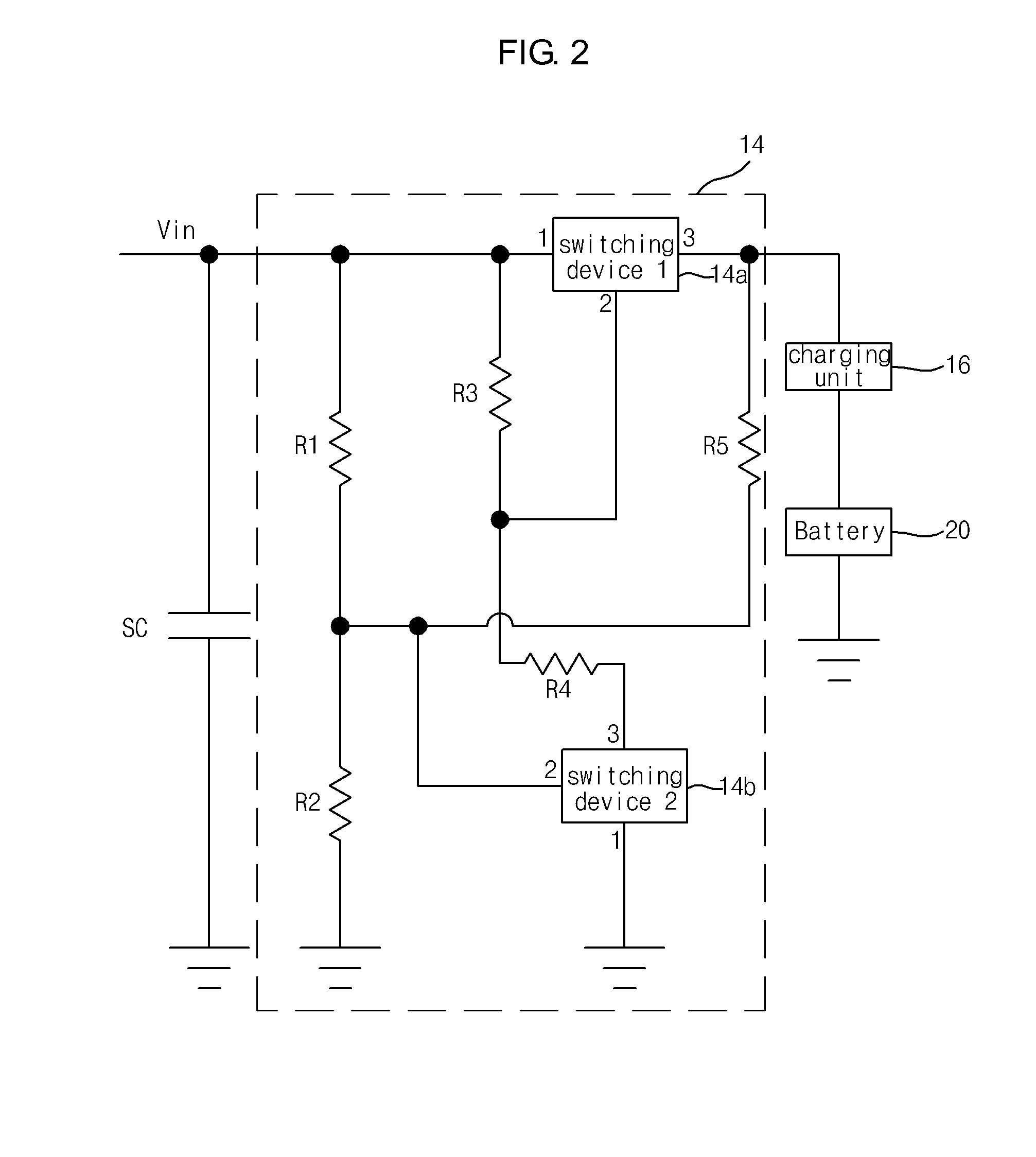
[0029]An electricity charging module 10 can be comprised of: a rectifying unit 12 for rectification of an external power input when it is an A.C. power; a storage capacitor (SC) for preliminarily storing of an electrical energy from an external power sou...


PUM


Abstract

An electricity charging module using a hysteresis switch includes a storage capacitor that preliminarily stores electrical energy supplied from an external power source, a charging unit for preventing over-charging or over-discharging through monitoring of the charging state of the rechargeable battery, and a hysteresis switch that has a larger turn-on voltage level than the turn-off voltage level, and located between the storage capacitor and the charging unit, thereby electrically connecting or disconnecting the storage capacitor with the charging unit. The hysteresis switch includes a first voltage dividing resistor pair that divides the voltage of an external power source by the resistance ratio of the first voltage dividing resistor pair, a second voltage dividing resistor pair whose one end is connected to a positive electrode terminal of the external power source, a first switching device whose control terminal is connected to the junction of the voltage dividing resistors of the second voltage dividing resistor pair, a second switching device whose control terminal is connected to the junction of the voltage dividing resistors of the first voltage dividing resistor pair, and a resistor that is connected to the junction between the first electrode terminal of the second switching device and the junction of the voltage dividing resistors of the first voltage dividing resistor pair.

Description

BACKGROUND OF THE INVENTION[0001]1. Field of the Invention[0002]The present invention relates to a hysteresis switch and an electricity charging module using the same, and more particularly, to a hysteresis switch capable of supplying a stable charging power to a rechargeable battery using a simple circuit configuration, and to an electricity charging module using such a hysteresis switch.[0003]2. Description of the Related Art[0004]It is well known that WSN is a wireless sensor network that collects information from various sensors via wireless communication; it is comprised of sensor nodes and sink nodes, wherein the sink node collects information from the sensor nodes and transmits this collected information to the outside. Not like a conventional network, the main purpose of such a wireless sensor network is to provide an automated remote information collection means instead of communication means; as network technologies including wireless personal area network (WPAN) and Ad-ho...

Claims


Application Information

Patent Timeline
IPC IPC(8): H02J7/00H03K17/687H03K17/60H03K17/56
CPCH02J7/0052H02J7/345H03K17/145H02M7/2176H03K17/14H02J2007/0059H02J2207/20H02J7/00
Inventor PARK, JUN-SEOKOH, HA-RYOUNGSEONG, YEONG-RAKROH, HYOUNG-HWANKIM, DO-WON
Owner KOOKMIN UNIV IND ACAD COOP FOUND
Why Eureka
Try Eureka