
Relay end-of-service-life forecasting device

Inactive Publication Date: 2011-10-06
YAMATAKE HONEYWELL CO LTD
View PDF1 Cites 19 Cited by
  • Summary
  • Abstract
  • Description
  • Claims
  • Application Information

AI Technical Summary

Benefits of technology

[0009]Given the present invention, the diagnosing of the end of the service life of the relay based on the time from a point in time wherein the application of the electric current to the relay coil is started by the controlling portion, or from the point in time that the application of the electric current to the relay coil is stopped by the controlling portion, until the point in time that the opening / closing of the relay is detected by the detecting portion makes it possible to forecast the end of the service life of the electromagnetic relay accurately, without a significant drop in the forecasting accuracy due to the effects of the load conditions or the environmental conditions.

Problems solved by technology

In the electrodes wherein uneven surfaces are formed, the electric discharges tend to initiate at the recessed / raised surfaces, and thus the recessed and raised portions propagate as the relay contacts are switched repetitively between ON and OFF multiple times, ultimately causing the electrodes, wherein the surfaces have been melted by the heat, to weld together, causing the contacts to become stuck perpetually in the ON state.
However, it is difficult to forecast the end of the service life of the electromagnetic relay accurately using the methods set forth above.
Moreover, in the method of calculating the service life by substituting load conditions, such as the electric current, into a specific end-of-service-life forecasting equation, as disclosed in JP '290, there will be cases wherein the load conditions anticipated in advance to not match the loads produced in actual use, due to, for example, the resistance values within the electromagnetic relays varying due to environmental factors such as the mechanism, the ambient gas, noise, and the like, and the accuracy of the forecast will suffer in such cases.

Method used


Image

  • Relay end-of-service-life forecasting device
  • Relay end-of-service-life forecasting device
  • Relay end-of-service-life forecasting device

Examples


Embodiment Construction

[0015]An example of the present invention will be described in detail below in reference to the drawings.

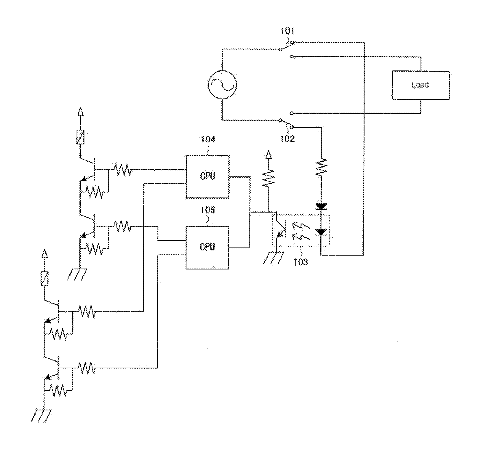
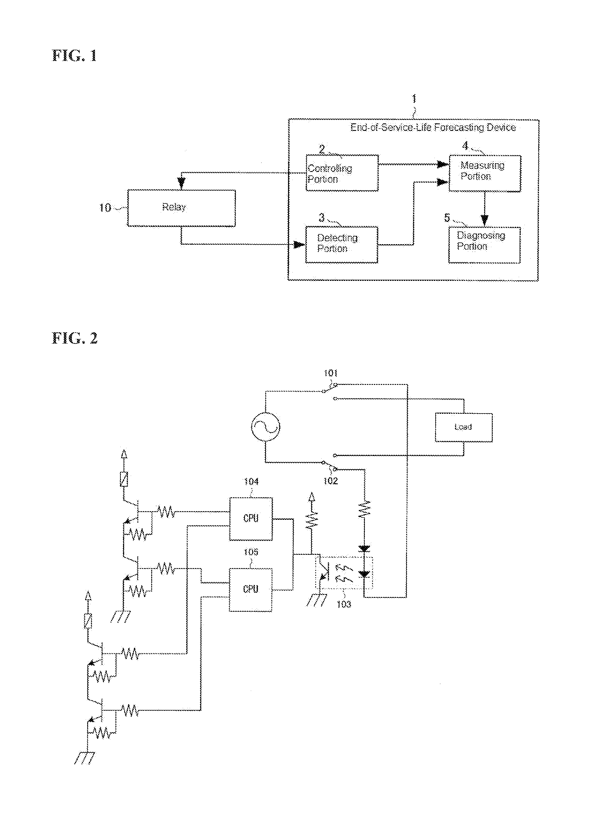
[0016]As illustrated in FIG. 1, the end-of-service-life forecasting device 1 in an example includes a controlling portion 2 for controlling the opening / closing of a relay 10; a detecting portion 3 for detecting the opening / closing of the contacts of the relay 10; a measuring portion 4 for measuring the time required to open / close the relay 10; and a diagnosing portion 5 for diagnosing the end of the service life of the relay 10 based on the measurement result by the measuring portion 4.

[0017]The controlling portion 2 is structured from an electric circuit for controlling the opening / closing of the relay 10. This controlling portion 2 provides notification to the measuring portion 4 when a control signal that is an instruction for opening / closing is outputted to the relay 10.

[0018]The detecting portion 3 is structured from a detecting device that detects the actual opening / closing...


PUM


Abstract

Forecasting the end of the service life of a relay more accurately due to the effects of the load conditions and the environmental conditions can occur through diagnosing the end of service life of the relay based on the time, until the point in time that the actual opening or closing of the relay is detected, from the point in time of the application of the power to the relay or the point in time of the end of application of power to the relay coil by the controlling portion. Forecasting the end of the service life of the relay based on time, increases accuracy because time is a value that is not affected by the external environment. Additionally, because the end of the service life is forecasted based on the actual opening / closing of the relay, not only is it possible to detect immediately a fault in the relay, but it is also possible to eliminate the effects due to individual differences.

Description

CROSS REFERENCE TO RELATED APPLICATIONS[0001]The present application claims priority under 35 U.S.C. §119 to Japanese Patent Application No. 2010-077247, filed Mar. 30, 2010, which is incorporated herein by reference.FIELD OF TECHNOLOGY[0002]The present invention relates to an end-of-service-life forecasting device for forecasting the end of the service life of an electromagnetic relay.BACKGROUND OF THE INVENTION[0003]Electromagnetic relays comprising a relay coil and a relay contact that is opened and closed through the application of an electric current to the relay coil are broadly and generally known. The relay contacts in such relays are switched mechanically between ON and OFF by magnetic forces generated by the coil. In mechanical switches, including this type of relay, when the contact is turned ON or OFF, an electric discharge is produced between the electrodes of the contacts, where the heat due to the electric discharge melts the surfaces of the electrodes, forming recess...

Claims


Application Information

Patent Timeline
IPC IPC(8): G01R31/327
CPCG01R31/3278H01H3/001H01H2071/044H01H47/002H01H11/0062
Inventor AKITA, DAISUKEKUMAZAWA, YUUICHI
Owner YAMATAKE HONEYWELL CO LTD
Learn More