Digital receiver techniques in radar detectors

a radar detector and digital receiver technology, applied in the field of radar detectors, can solve the problems of increasing the difficulty of achieving a good compromise between response time and sensitivity using narrow-band analog detection methods, and the slow response time of analog detection,

Active Publication Date: 2011-10-06
ESCORT INC
View PDF36 Cites 25 Cited by
  • Summary
  • Abstract
  • Description
  • Claims
  • Application Information

AI Technical Summary

Benefits of technology

[0018]In some embodiments, a pseudo-random channel pattern is utilized by the processor for advancing to the next channel of the plurality of channels. In other embodiments, the next channel of the plurality of channels is randomly selected by the processor from the plurality of channels. In these embodiments, the processor may statistically analyze a number of times a channel of the plurality of channels has been analyzed to ensure each channel of the plurality of channels is periodically analyzed.

Problems solved by technology

A problem with using an analog detection technique is that the analog detection has a slow response time.
Unfortunately, analog detection methods involving FM demodulators only allow detectors to look at a narrow frequency bands at specific times, in order to achieve good sensitivity to RADAR signals over any noise.
In other words, it has become more difficult to achieve a good compromise between response time and sensitivity using narrow-band analog detection methods.
This problem has become even more apparent lately as more RADAR guns have started to implement short pulsed sources, known as POP-mode RADAR.
Even the top of the line models of the contemporary detectors struggle with identifying this shorter duration POP-mode and the detector only alerts to the pulsed waves about one out of every 10 bursts.

Method used


Image

  • Digital receiver techniques in radar detectors
  • Digital receiver techniques in radar detectors
  • Digital receiver techniques in radar detectors

Examples


Embodiment Construction

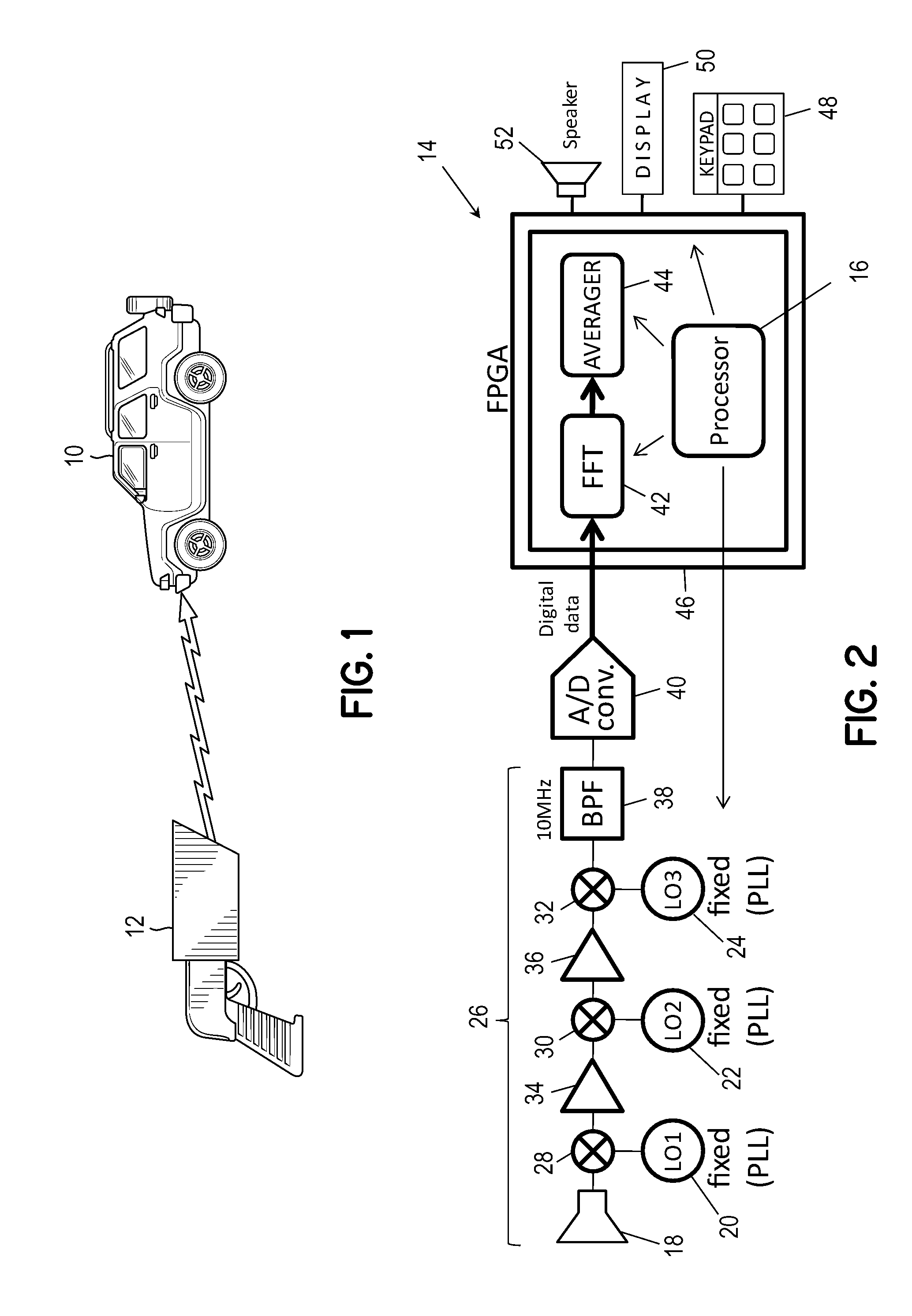
[0031]Embodiments of the invention implement direct IF sampling techniques. This method does not involve an FM demodulator. An intermediate frequency of the detector may be digitized by a wide band analog-to-digital converter and the resulting digital stream of data may then be processed completely in the digital domain, making the embodiments truly digital radar detectors. Embodiments employing digital techniques also realize, through wide band digital sampling, a significant improvement in response time, as well as increase in sensitivity.

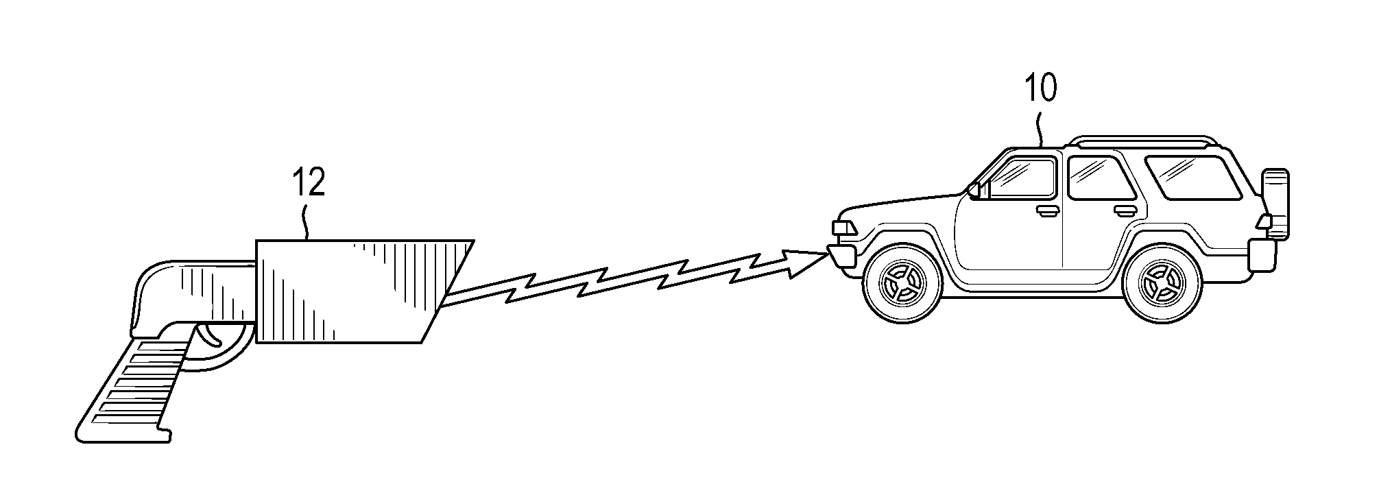
[0032]Referring now to FIG. 1, a vehicle 10 is illustrated in operation on a roadway, under exposure to radio frequency signals from a variety of sources including police sources, such as RADAR gun 12, as well as other non-police sources of interference from surrounding businesses, homes, etc. (not shown). Vehicle 10 is equipped with a RADAR detector capable of detecting both the police and non-police sources. In some embodiments, the RADAR detec...


PUM


Abstract

A method and apparatus are provided for detecting a RADAR signal. RADAR channel data in a frequency range is received, where the frequency range is divided into a plurality of equally wide channels. The received RADAR channel data is digitally processed and analyzed to identify a signal in the RADAR channel data in the frequency range. The frequency range is advanced to a next channel of the plurality of channels, where the frequency range of the next channel of the plurality of channels is nonsequential with the frequency range of the first channel. The steps of receiving, processing, and analyzing are repeated for the next channel of the plurality of channels.

Description

CROSS-REFERENCE TO RELATED APPLICATIONS[0001]This application is a continuation-in-part of U.S. application Ser. No. 12 / 749,728, entitled “DIGITAL RECEIVER TECHNIQUES IN RADAR DETECTORS,” filed on Mar. 30, 2010, the entirety of which is incorporated by reference herein.FIELD OF THE INVENTION[0002]The present invention relates to radar detectors, and more particularly to radar detectors which detect police radar signals before the vehicle is within the detection range of the police radar unit.BACKGROUND OF THE INVENTION[0003]RADAR detectors warn drivers of the use of police RADAR, and the potential for traffic citations if the driver exceeds the speed limit. The FCC has allocated several regions of the electromagnetic spectrum for police RADAR use. The bands used by police RADAR are generally known as the X, K and Ka bands. Each relates to a different part of the spectrum. The X and K bands are relatively narrow frequency ranges, whereas the Ka band is a relatively wide range of freq...

Claims


Application Information

Patent Timeline
Patent Type & Authority Applications(United States)
IPC IPC(8): G01S7/42
CPCG01S7/022G01S7/021G01S7/4806G01S13/88
Inventor CHERNUKHIN, IGOR
Owner ESCORT INC
Why Eureka
Try Eureka