
Projection system with touch-sensitive projection image

a projection system and touch-sensitive technology, applied in the field of projection systems, can solve the problems of inconvenient control of projection images, and inconvenient control of projection images, and achieve the effect of improving the user experience and improving the control efficiency

Inactive Publication Date: 2011-10-06
COMPAL COMMUNICATIONS INC
View PDF22 Cites 88 Cited by
  • Summary
  • Abstract
  • Description
  • Claims
  • Application Information

AI Technical Summary

Benefits of technology

[0007]The present invention provides a projection system with a touch-sensitive projection image. By placing one or more fingers on the projection image, a desired controlling action is performed in an intuitive, convenient and user-friendly manner. In such way, the problem of using the auxiliary light source in the conventional projection system will be avoided.
[0008]The present invention also provides a projection system with a touch-sensitive projection image in order to simplify the calculating complexity, enhance the calculating accuracy and increase the interactive speed.

Problems solved by technology

This method of controlling the projection image is not user-friendly.
Since the auxiliary light source is additionally held by the user's hand, the conventional method of controlling the projection image is inconvenient.
Moreover, the conventional method of controlling the projection image still has some other drawbacks.
For example, since the brightness and / or the color of the projection image and the background color of the projection screen may adversely affect the accuracy of detecting the change of the pointing light beam, the calculating complexity is very high and the calculating accuracy is low.
In such way, the interactive speed of controlling the projection image is usually unsatisfied.

Method used


Image

  • Projection system with touch-sensitive projection image
  • Projection system with touch-sensitive projection image
  • Projection system with touch-sensitive projection image

Examples


Embodiment Construction

[0021]The present invention will now be described more specifically with reference to the following embodiments. It is to be noted that the following descriptions of preferred embodiments of this invention are presented herein for purpose of illustration and description only. It is not intended to be exhaustive or to be limited to the precise form disclosed.

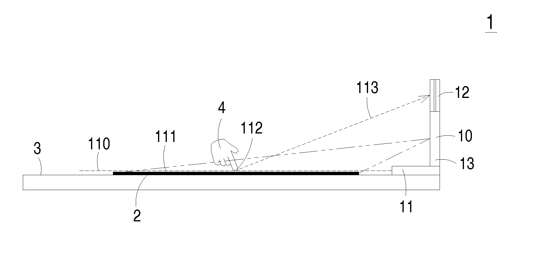
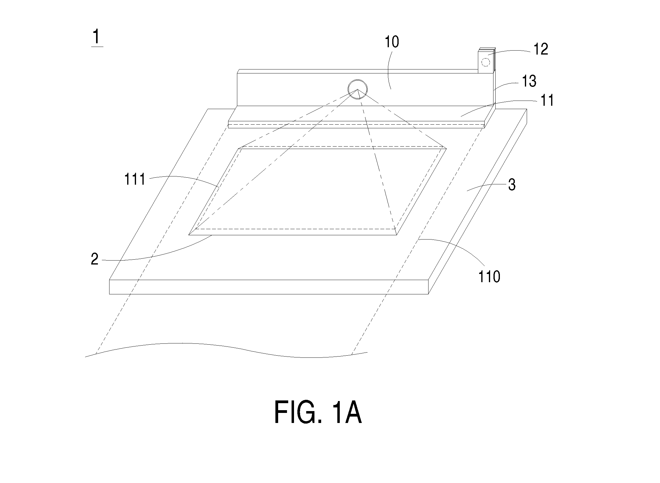
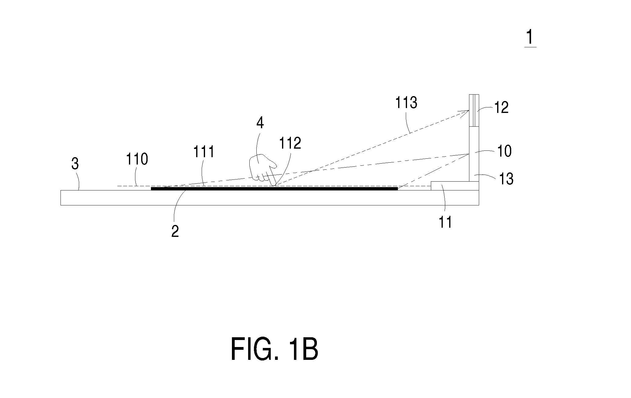
[0022]FIG. 1A is a schematic perspective view illustrating a projection system with a touch-sensitive projection image according to an embodiment of the present invention. FIG. 1B is a schematic side view illustrating the projection system of FIG. 1A. Please refer to FIGS. 1A and 1B. The projection system 1 comprises an image projector 10, an invisible light transmitter 11 and an invisible light sensor 12. The image projector 10 is used to project a projection image 2 on a physical plane 3. The projection image 2 is a visible light image. In addition, the projection image 2 comprises an input zone or an input mark (not shown). Th...


PUM


Abstract

A projection system includes an image projector, an invisible light transmitter and an invisible light sensor. The image projector is used for projecting a projection image on a physical plane. The invisible light transmitter is used for generating an invisible light plane, which is parallel with the physical plane. The invisible light sensor is in communication with the image projector. When a pointing object is placed on a touching point, an invisible light beam reflected from the pointing object is received by the invisible light sensor. According to the invisible light beam, a sensing signal indicative of a spatial coordinate position of the touching point is acquired and transmitted to the image projector. The image projector recognizes and calculates the spatial coordinate position of the touching point according to the sensing signal and performs a controlling action according to the spatial coordinate position.

Description

CLAIM OF PRIORITY[0001]This application claims priority to Taiwanese Patent Application No. 099110225 filed on Apr. 1, 2010.FIELD OF THE INVENTION[0002]The present invention relates to a projection system, and more particularly to a projection system with a touch-sensitive projection image.BACKGROUND OF THE INVENTION[0003]With increasing development of the information generation, the projection system with the portable and easy-to-use benefits is widely used in conference, office, school and home. For most attendants in meetings or most businessmen, the projection system is usually used to make a presentation, hold a meeting or give a lecture.[0004]The conventional projection system is usually operated with an image signal source (e.g. a portable computer or a portable communication device). The image outputted from the image signal source is projected onto a projection screen through the projection system. For controlling the projection image on the projection screen, a mouse, a ke...

Claims


Application Information

Patent Timeline
IPC IPC(8): G06F3/042
CPCG06F3/0426G06F3/0425
Inventor TSU, FU-KUAN
Owner COMPAL COMMUNICATIONS INC
Learn More