Pen-like optical input device

a technology of optical input and pen, which is applied in the direction of instruments, computing, electric digital data processing, etc., can solve problems such as errors in locating the cursor, and achieve the effect of increasing the sensing range of the light sensing unit in the body and good image quality

Inactive Publication Date: 2011-10-06
KYE SYST CORP
View PDF2 Cites 11 Cited by
  • Summary
  • Abstract
  • Description
  • Claims
  • Application Information

AI Technical Summary

Benefits of technology

[0012]According to the pen-like optical input device of the present invention, the light source, the lens and the light sensing unit are disposed in the body, and the normal of the light receiving surface of the light sensing unit inclines to the optical axis of the lens, such that a sensing range of the light sensing unit in the body is increased. Therefore, when the optical axis of the lens inclines to the work surface so that an object distance from the lens to the work surface is changed, an inclined angle between the optical axis and the normal of the work surface is compensated by the angle between the normal of the light receiving surface and the optical axis, such that the reflected light ray after being refracted by the lens entirely falls into the sensing range of the optical sensing unit, thereby maintaining a good image quality.

Problems solved by technology

However, in the case that a focal length of the lens and a sensing range of the optical sensor are fixed, when the object distance between the lens and the work surface changes, an imaging range formed after the reflected light ray is refracted by the lens fails to fall into the focus.
For instance, the imaging range of the reflected light ray exceeds the sensing range of the optical sensor, which results in the generation of a blur image since the reflected light ray cannot be completely imaged on the optical sensor, causing confusion when the optical sensor reads an optical signal and degrading the quality (for example contrast) of the image detected by the optical sensor, and even resulting in errors in locating the cursor.

Method used


Image

  • Pen-like optical input device
  • Pen-like optical input device
  • Pen-like optical input device

Examples


first embodiment

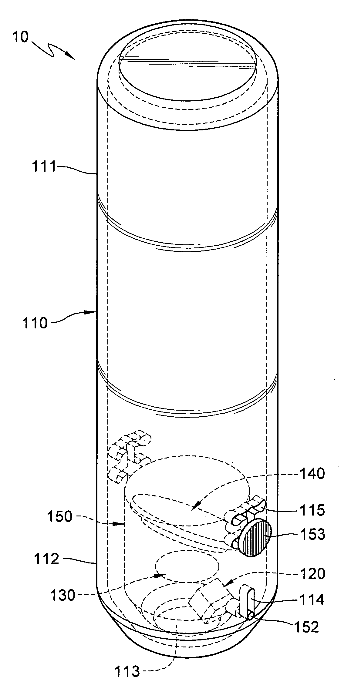
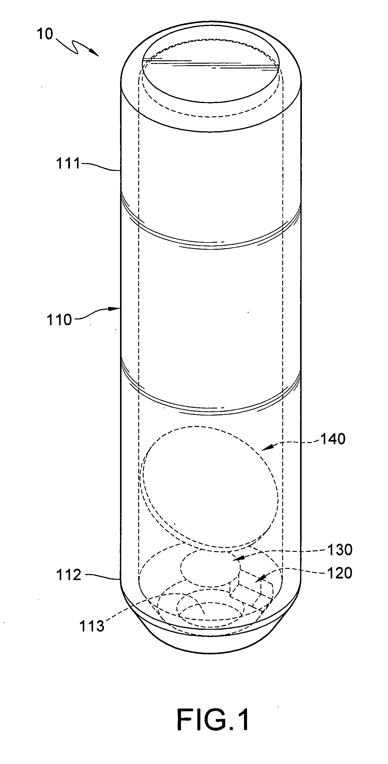
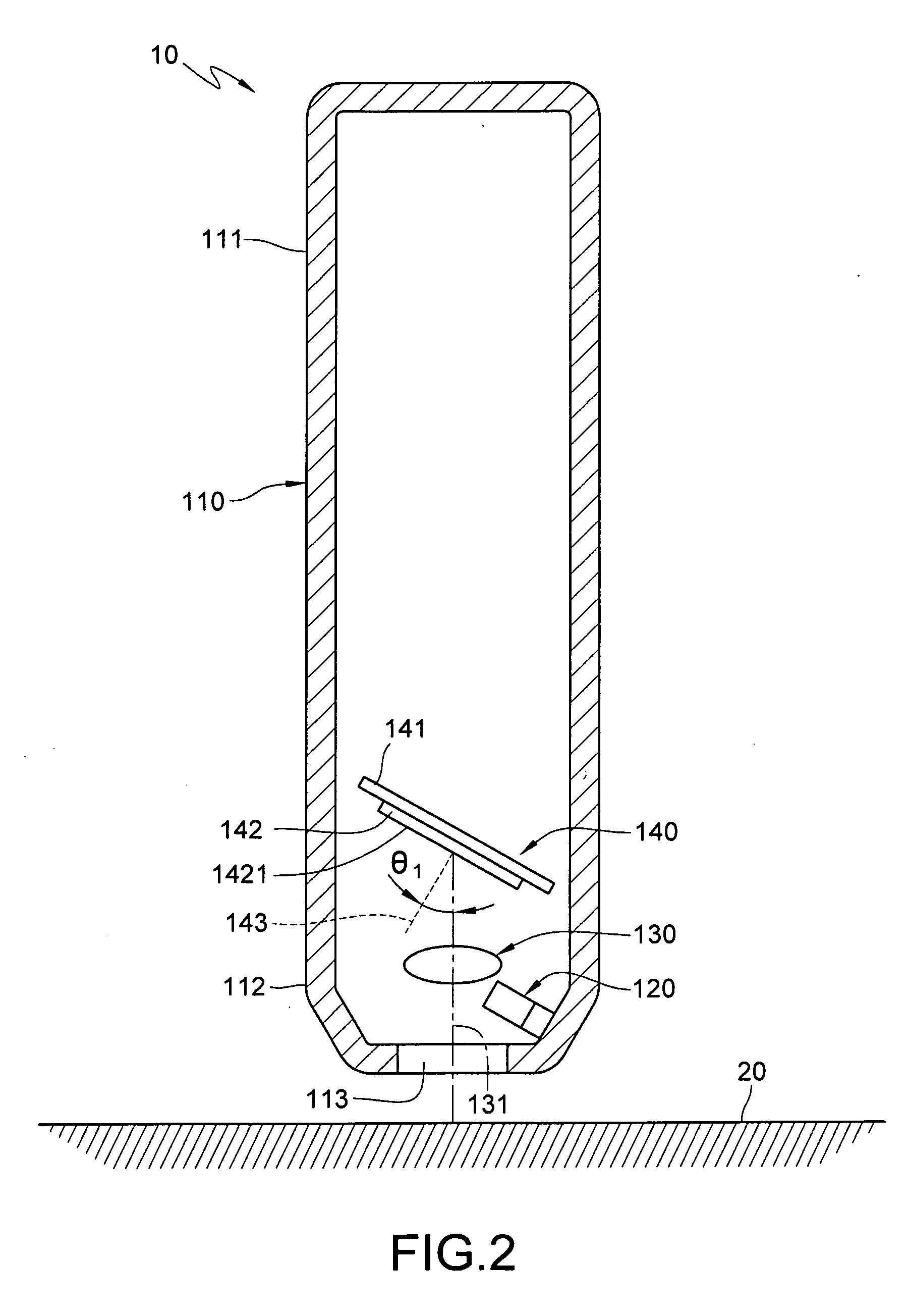
[0024]As shown in FIGS. 1 and 2, a pen-like optical input device 10 according to the present invention comprises a body 110, a light source 120, a lens 130 and a light sensing unit 140. The body 110 is a hollow round pole, and forms a penholder-like shape. The body 110 comprises a first end 111 and a second end 112 opposite to each other, and comprises a light-transmissive hole 113 on an end surface of the second end 112. The light source 120, the lens 130 and the light sensing unit 140 are disposed at positions near the second end 112 in the body 110. The light source 120 may be but is not limited to a light emitting diode (LED), and may also be a light emitting component capable of emitting directional light, for example, a laser diode. The lens 130 and the light sensing unit 140 are corresponding to the light-transmissive hole 113 of the body 110, and the lens 130 is located between the light sensing unit 140 and the light-transmissive hole 113. The lens 130 may be of various typ...

second embodiment

[0030]Referring to FIGS. 4 and 5, a pen-like optical input device 10 according to the present invention comprises a body 110 and an optical-mechanical module 150. The body 110 is a hollow round pole with a penholder-like shape. The body 110 comprises a first end 111 and a second end 112 opposite to each other, in which an end surface of the second end 112 comprises a light-transmissive hole 113, and two longitudinal grooves 114 and 114′ and two horizontal grooves 115 connected to the inside of the body 110 are respectively disposed on two opposite sides where the second end 112 is jointed with the end surface. The two longitudinal grooves 114 and 114′ are disposed on the body 110 sequentially from the second end 112 to the first end 111 along an axis direction of the body 110. The horizontal grooves 115 are disposed on the body 110 along a direction perpendicular to the two longitudinal grooves 114 and 114′. The two horizontal grooves 115 are disposed on the two opposite ends of the...


PUM


Abstract

A pen-like optical input device includes a body. A light source, a light sensing unit and a lens are disposed in the body, a light ray is emitted by the light source to the outside of the body, and a reflected light ray is generated outside the body. The reflected light ray then is received by the light sensing unit after being refracted by the lens, in which the light sensing unit has a light receiving surface, and a normal of the light receiving surface inclines to an optical axis of the lens, thereby forming an angle with the optical axis.

Description

CROSS-REFERENCE TO RELATED APPLICATIONS[0001]This non-provisional application claims priority under 35 U.S.C. §119(a) on Patent Application No(s). 099109980 filed in Taiwan, R.O.C. on Mar. 31, 2010, the entire contents of which are hereby incorporated by reference.BACKGROUND OF THE INVENTION[0002]1. Field of Invention[0003]The present invention relates to an optical input device, and more particularly to a pen-like optical input device.[0004]2. Related Art[0005]With the rapid development of science and technology, computer operating systems are widely used in daily life. Generally speaking, when operating a computer operating system, a user must control the movement of a cursor through peripheral input devices such as a mouse, a touchpad or a trackball, so as to input operating instructions on a window interface of the computer. Taking an optical mouse as an example, in addition to functions of the common optical mouse such as moving the cursor and clicking / selecting page data, curr...

Claims


Application Information

Patent Timeline
Patent Type & Authority Applications(United States)
IPC IPC(8): G06F3/033
CPCG06F3/03545G06F3/0317
Inventor LI, SHEAU-LINLEE, TSU-NANLAI, CHIEN-MO
Owner KYE SYST CORP
Why Eureka
Try Eureka