
Liquid ejection apparatus and storage medium storing program therefor

Active Publication Date: 2011-10-06
BROTHER KOGYO KK
View PDF14 Cites 0 Cited by
  • Summary
  • Abstract
  • Description
  • Claims
  • Application Information

AI Technical Summary

Benefits of technology

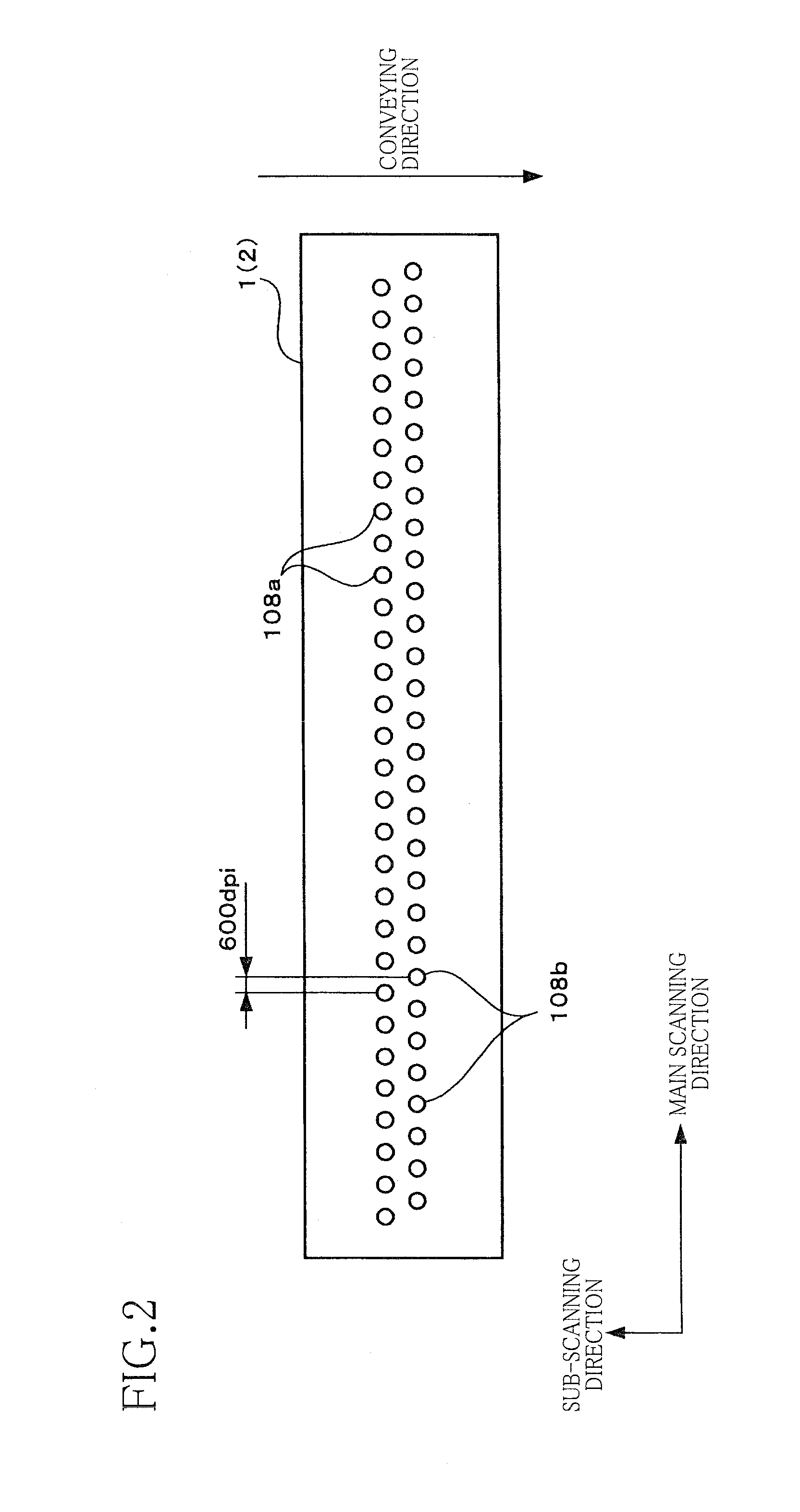
[0006]Where nozzles for ejecting the pretreatment liquid are adjacent to each other in a main scanning direction perpendicular to a sheet conveying direction and are arranged at different positions in the sheet conveying direction, timings for ejecting the pretreatment liquid are different from each other between two pixel areas arranged at the same position on the sheet in the sheet conveying direction and adjacent to each other in the main scanning direction in a recording resolution. In this case, pretreatment liquid ejected first onto one pixel area may spread over pixel areas adjacent to the one pixel area, whereby pretreatment liquid ejected thereafter may be unfortunately overlaid on an area over which the pretreatment liquid ejected first has spread, before the pretreatment liquid ejected first has been landed and permeated the sheet. In this overlaying area, the pretreatment liquid ejected later tends not to sufficiently permeate the sheet and tends to remain in a liquid-layer state. Thus, when the ejected ink has been landed on the pretreatment liquid in the liquid-layer state, the ink forms a dot having a size smaller than a desired size and having a relatively high density. This may cause streaks and density inconsistencies on a recorded image, lowering a recording quality.
[0007]This invention has been developed in view of the above-described situations, and it is an object of the present invention to provide a liquid ejection apparatus and a storage medium storing a program executed in the liquid ejection apparatus which can prevent occurrence of streaks and density inconsistencies on a recorded image.
[0011]In the image recording apparatus constructed as described above, it is possible to prevent that, before the second liquid ejected later from the second ejection opening of the pair of second ejection openings sufficiently permeates the recording medium, the second liquid ejected later is overlaid, on the recording medium, on the second liquid ejected first from the second ejection opening of the pair of second ejection openings. As a result, both of the second liquids ejected respectively from the second ejection openings sufficiently permeate the recording medium and expand or spread over their respective desired areas, reducing an area of the second liquid remaining in a liquid-layer state. Thus, when the ejected first liquid has been landed on the second liquid, the first liquid forms a dot having desired size and density. Accordingly, streaks and inconsistencies in density are less likely to occur on the recorded image, thereby preventing a lowering of an image quality.

Problems solved by technology

This may cause streaks and density inconsistencies on a recorded image, lowering a recording quality.

Method used


Image

  • Liquid ejection apparatus and storage medium storing program therefor
  • Liquid ejection apparatus and storage medium storing program therefor
  • Liquid ejection apparatus and storage medium storing program therefor

Examples


first embodiment

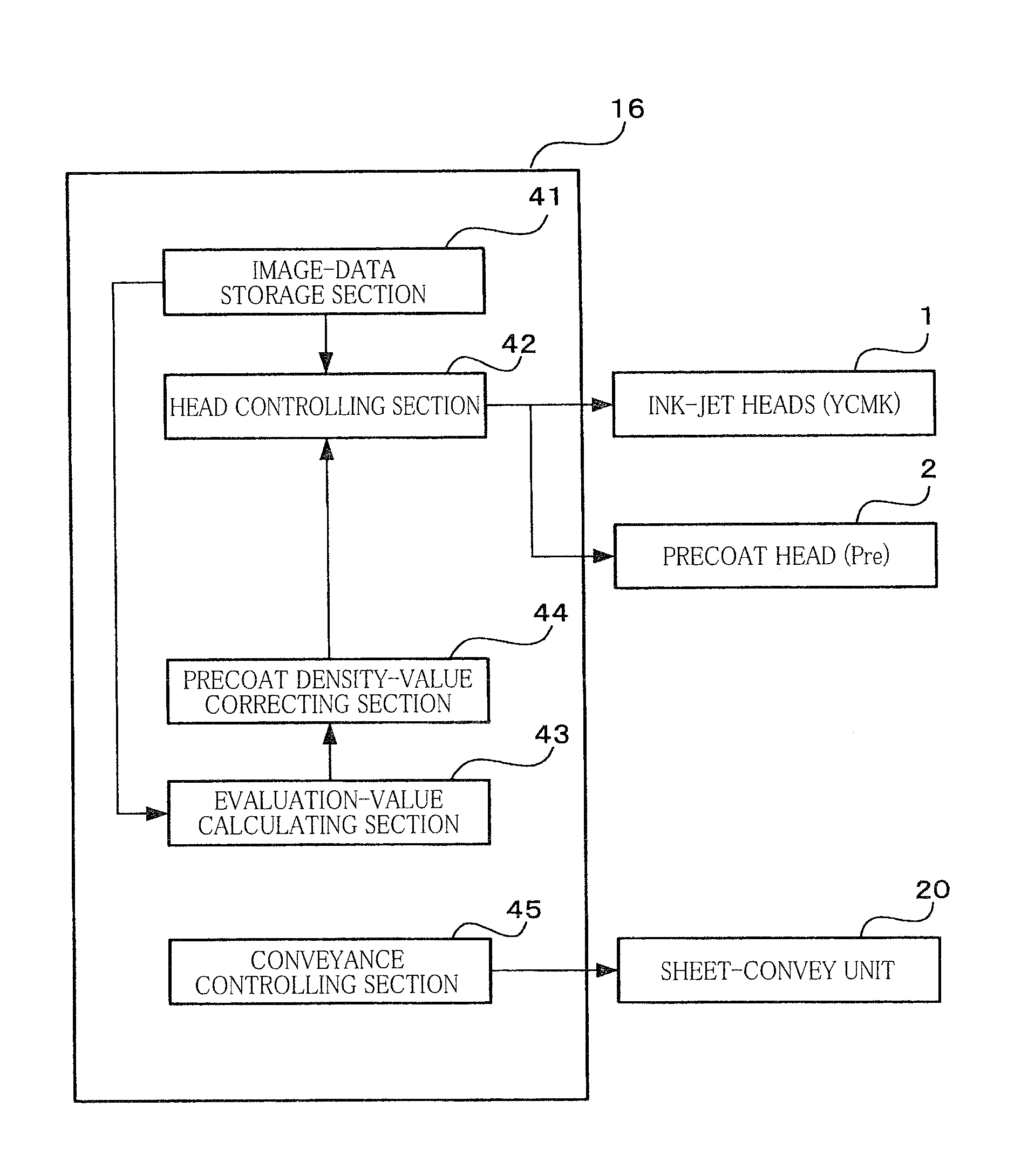
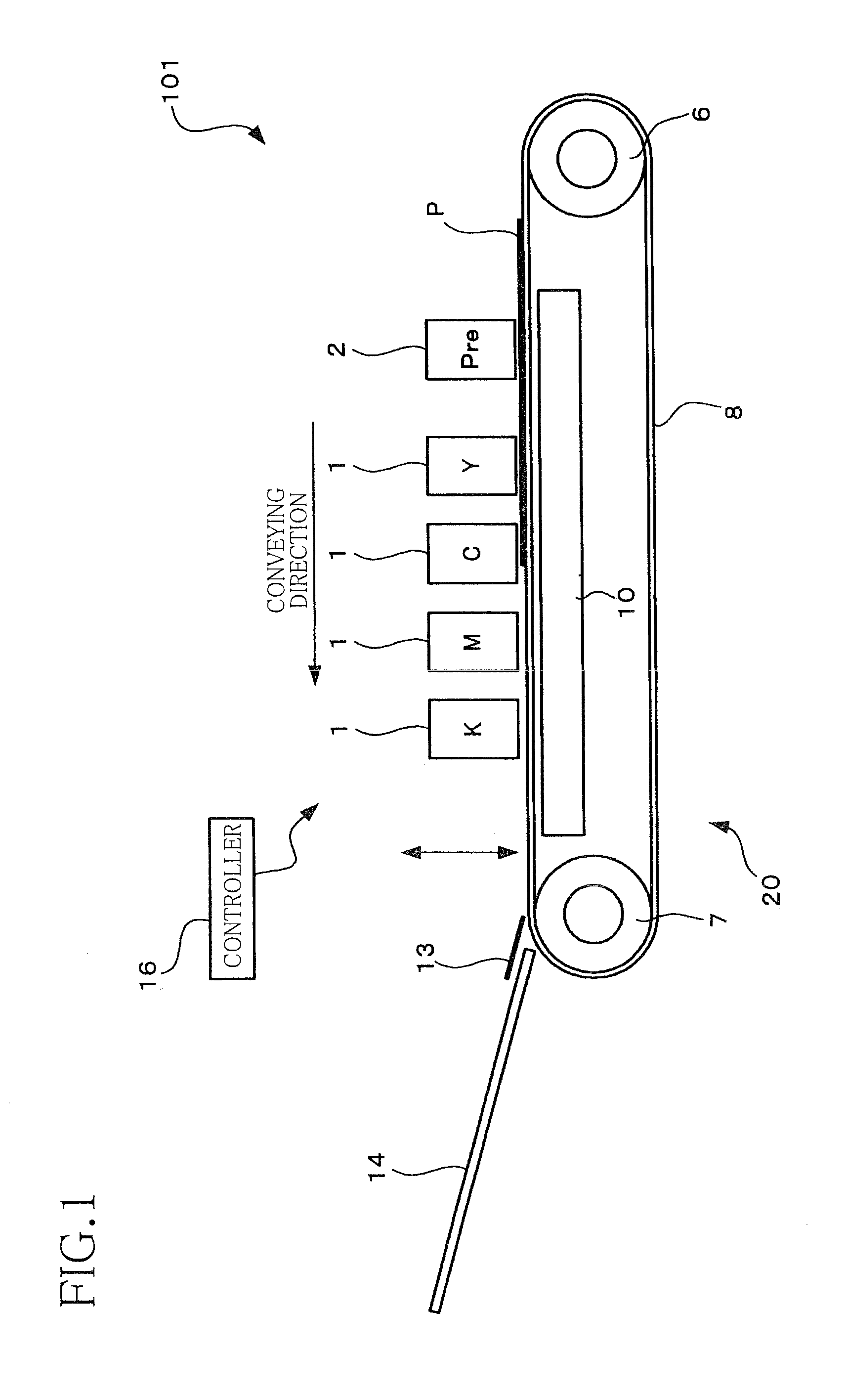
[0030]As shown in FIG. 1, an ink-jet printer 101 includes a sheet-convey unit 20 as one example of a conveying mechanism, four ink-jet heads 1 each as one example of a first-liquid ejection head, a precoat head 2 as one example of a second-liquid ejection head, and a controller 16. The sheet-convey unit 20 is configured to convey or feed a sheet P from a right side toward a left side in FIG. 1. The ink-jet heads 1 are configured to eject ink droplets onto the sheet P conveyed by the sheet-convey unit 20. Specifically, the ink-jet heads 1 respectively eject inks (as one example of first liquid) of respective four colors, namely, yellow (Y), cyan (C), magenta (M), and black (K). The precoat head 2 is configured to eject liquid droplets of precoat liquid (Pre) as one example of second liquid. The precoat liquid has a property of coagulating or precipitating color components (pigment compositions) of each ink. The controller 16 is configured to control entire operations of the ink jet p...

second embodiment

[0049]There will be next explained a second embodiment of the present invention. It is noted that, the same reference numerals as used in the first embodiment are used to designate corresponding elements and functioning sections, and an explanation thereof is dispensed with. As shown in FIG. 7, in an ejection face of a precoat head 202 of an ink-jet printer 201, four ejection-opening groups each constituted by a plurality of the ejection openings 108c or 108d arranged at pitches of 600 dpi in the main scanning direction are arranged in the main scanning direction in a staggered fashion. Each of ejection-opening groups located on an upstream side in the conveying direction (the sub-scanning direction) is constituted by the ejection openings 108c, and each of ejection-opening groups located on a downstream side in the conveying direction is constituted by the ejection openings 108d. Thus, when the image is recorded on the conveyed sheet P, the ink droplets ejected from the ejection op...

third embodiment

[0054]There will be next explained a third embodiment of the present invention. As shown in FIG. 10, a controller 316 of an ink-jet printer 301 of this third embodiment is different from the controller 16 of the first embodiment in that the controller 316 does not include the evaluation-value calculating section 43 and the precoat density-value correcting section 44 and includes a precoat density-value determining section 346. In this third embodiment, each density value is quantized into five values respectively corresponding to non-ejection, a small-sized droplet, a medium-sized droplet, a large-sized droplet and an extra-large sized droplet. These density values have the following relationship in size: a value corresponding to the non-ejection<a value corresponding to the small droplet<a value corresponding to the medium droplet<a value corresponding to the large droplet<a value corresponding to the extra-large droplet. It is noted that the larger the density value, a larger amou...


PUM


Abstract

A liquid ejection apparatus, including: a conveying mechanism which conveys a recording medium in a predetermined conveying direction, a first head for ejecting first liquid; a second head for ejecting second liquid for coagulating or precipitating components of the first liquid, and disposed upstream of the first head in the conveying direction; and a controller, wherein a pair of second ejection openings of the second head are arranged side by side, wherein the second liquid is to be ejected respectively from the pair of second ejection openings at different timings onto a pair of unit areas arranged side by side, and wherein the controller controls the second head so as to reduce an amount of the second liquid ejected from at least one of the pair of second ejection openings, where an amount of the second liquid to be ejected from one of the pair of second ejection openings at an earlier one of the different timings is equal to or larger than a first predetermined value.

Description

CROSS REFERENCE TO RELATED APPLICATION[0001]The present application claims priority from Japanese Patent Application Nos. 2010-078499 filed on Mar. 30, 2010, and 2010-125162 filed on May 31, the disclosure of which is herein incorporated by reference in its entirety.BACKGROUND OF THE INVENTION[0002]1. Field of the Invention[0003]The present invention relates to a liquid ejection apparatus configured to eject first liquid from ejection openings onto a recording medium after ejecting second liquid for coagulating or precipitating components of the first liquid, and relates to a storage medium storing a program executed in the liquid ejection apparatus.[0004]2. Description of the Related Art[0005]There is known a line ink-jet printer configured to eject pretreatment liquid for coagulating or precipitating color components of ink, onto a position at which a dot is to be formed on a sheet, before ejecting an ink droplet, in order to reduce spreading of the dot.SUMMARY OF THE INVENTION[00...

Claims


Application Information

Patent Timeline
IPC IPC(8): B41J29/38
CPCB41J2/2114
Inventor ITOGAWA, YOSHIHIRO
Owner BROTHER KOGYO KK
Learn More