Light source unit and projector

a technology which is applied in the field of light source unit and projector, can solve the problems of reducing the amount of luminescent luminous light emitted from the source, deteriorating of luminescent material by heat or burning, and reducing the amount of luminescent luminous light emitted, so as to reduce power consumption during projection, prevent heat deterioration, and reduce power consumption.

Active Publication Date: 2011-10-06
CASIO COMPUTER CO LTD
View PDF1 Cites 12 Cited by
  • Summary
  • Abstract
  • Description
  • Claims
  • Application Information

AI Technical Summary

Benefits of technology

[0014]The invention has been made in view of the problems inherent in the related art, and an object thereof is to provide a light source unit comprising an excitation light source and a luminescent wheel on which a luminescent material layer is laid, wherein power consumption can be reduced while preventing the de

Problems solved by technology

In these projectors, although the amount of luminescent luminous light emitted from the luminescent material can be increased by increasing the output of the excitation light source, when the output of the excitation light source is increased, there has been caused a fear that the luminescent material is heated and the

Method used


Image

  • Light source unit and projector
  • Light source unit and projector
  • Light source unit and projector

Examples


Embodiment Construction

[0022]Hereinafter, a preferred mode for carrying out the invention will be described by use of the accompanying drawings.

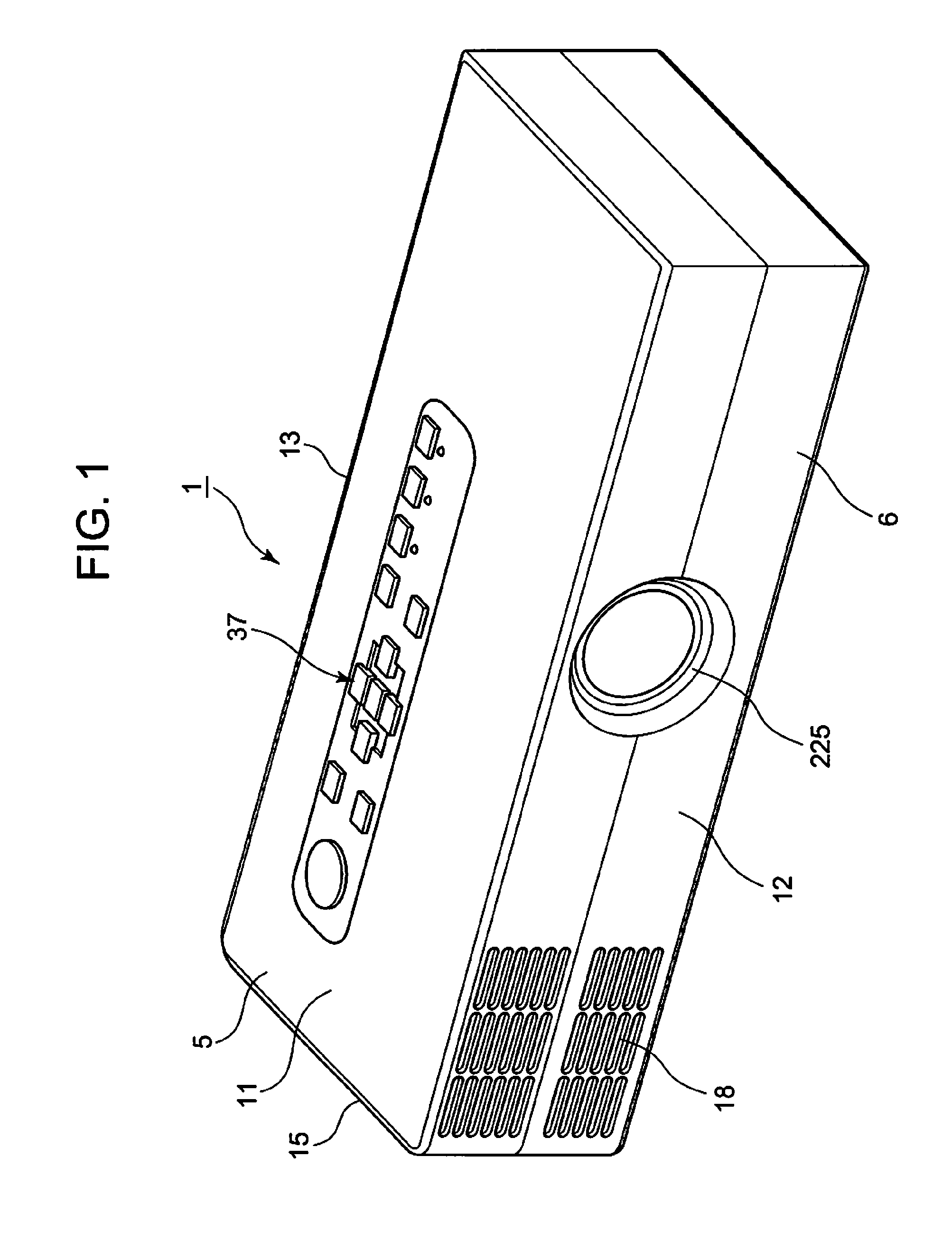
[0023]FIG. 1 is a perspective view showing an external appearance of a projector.

[0024]In this embodiment, when the left and right of a projector 1 are described, leftward and rightward directions with respect to a projecting direction of the projector 1 are meant, and when the front and rear of the projector 1 are described, forward and rearward directions with respect to the projecting direction of the projector 1 and a traveling direction of a light beam are meant.

[0025]As is shown in FIG. 1, a projector 1 is a small projector 1 which has a substantially rectangular parallelepiped geometry and which is so small as to be placed on the inner surface of the hand. The projector 1 includes an upper case 5 and a lower case 6 which are made to cover an interior of the projector 1.

[0026]When the upper case 5 and the lower case 6 are fitted together, a front panel 12 is...


PUM


Abstract

A projector is provided which can reduce power consumption while preventing the deterioration of a luminescent material by heat by controlling a luminescent wheel to rotate or stop rotating. The projector of the invention includes a light source unit having an excitation light source, a luminescent wheel on which a luminescent material layer is laid circumferentially which becomes luminous using light emitted from the excitation light source as excitation light and a wheel motor for driving the luminescent wheel, a display device, a light guiding optical system which guides light emitted from the light source unit to the display device, a projection side optical system which projects projection light generated in the display device, and a motor control part which determines whether to stop or drive the wheel motor in such a state that excitation light is shone on to the luminescent material layer by the excitation light source.

Description

CROSS-REFERENCE TO RELATED APPLICATIONS[0001]This application is based upon and claims the benefit of priority under 35 USC 119 of Japanese Patent Application No. 2010-82695 filed on Mar. 31, 2010, the entire disclosure of which, including the description, claims, drawings and abstract thereof, is incorporated herein by reference.BACKGROUND OF THE INVENTION[0002]1. Field of the Invention[0003]The present invention relates to a light source unit and a projector which includes this light source unit.[0004]2. Description of the Related Art[0005]In these days, data projectors are used on many occasions as image projection apparatuses which project images including images of screens and video images of personal computers, as well as images based on image data which is stored in memory cards on to a screen.[0006]In projectors of the type described above, conventionally, projectors using a high-intensity discharge lamp as a light source have been the mainstream of projectors. However, in r...

Claims


Application Information

Patent Timeline
IPC IPC(8): G03B21/14F21V9/16H05B37/02F21V9/40
CPCG03B21/14G03B21/206G03B21/204G03B21/16G03B21/2086G03B21/20
Inventor SHIBASAKI, MAMORU
Owner CASIO COMPUTER CO LTD
Why Eureka
Try Eureka