Rechargeable Battery

a rechargeable battery and battery technology, applied in the field of rechargeable batteries, can solve the problems of low strength the inability to fasten the bus bar and the electrode terminal with large torque, and the size of the electrode terminal is limited to a predetermined size, so as to improve the structure of the electrode terminal, reduce failures, and increase the fastening force

Active Publication Date: 2011-10-06
ROBERT BOSCH GMBH +1
View PDF0 Cites 54 Cited by
  • Summary
  • Abstract
  • Description
  • Claims
  • Application Information

AI Technical Summary

Benefits of technology

[0012]An aspect of an embodiment of the present invention is directed to a rechargeable battery having an improved electrode terminal structure allowing for an increased fastening force when attaching the electrode terminal to a bus bar when forming a battery module. The increased fastening force reduces failures due to external vibration and impact. Additionally, the increased fastening force increases contact area between the bus bar and the electrode terminal, reducing contact resistance.

Problems solved by technology

Additionally, customarily, due to these considerations, the size of the electrode terminal is limited to a predetermined size.
When the electrode terminals are formed with aluminum or copper, when fastening the bus bar and the electrode terminals, the bus bar and the electrode terminals cannot be fastened with large torque as a result of the low strength of the electrode terminals.
Thereby, in an environment having much vibration and impact, such as in an electric vehicle or a hybrid electric vehicle, when rechargeable batteries are formed into a battery module, the connection between the bus bar and the electrode terminals (that are fastened with low torque) may be released, causing structural instability of the battery module.
Additionally, the increased fastening force increases contact area between the bus bar and the electrode terminal, reducing contact resistance.

Method used


Image

  • Rechargeable Battery
  • Rechargeable Battery
  • Rechargeable Battery

Examples


Embodiment Construction

[0032]Hereinafter, exemplary embodiments of the present invention will be described in detail with reference to the accompanying drawings such that those having ordinary skill in the art to which the present invention pertains may implement the technological concept of the present invention. However, the present invention may be implemented in various different ways, and is not limited to the following exemplary embodiments. Like reference numerals designate like constituent elements throughout the specification.

[0033]Throughout this specification and the claims that follow, when it is described that an element is “coupled” to another element, the element may be “directly coupled” to the other element, or it may be “electrically coupled” to the other element through a third element.

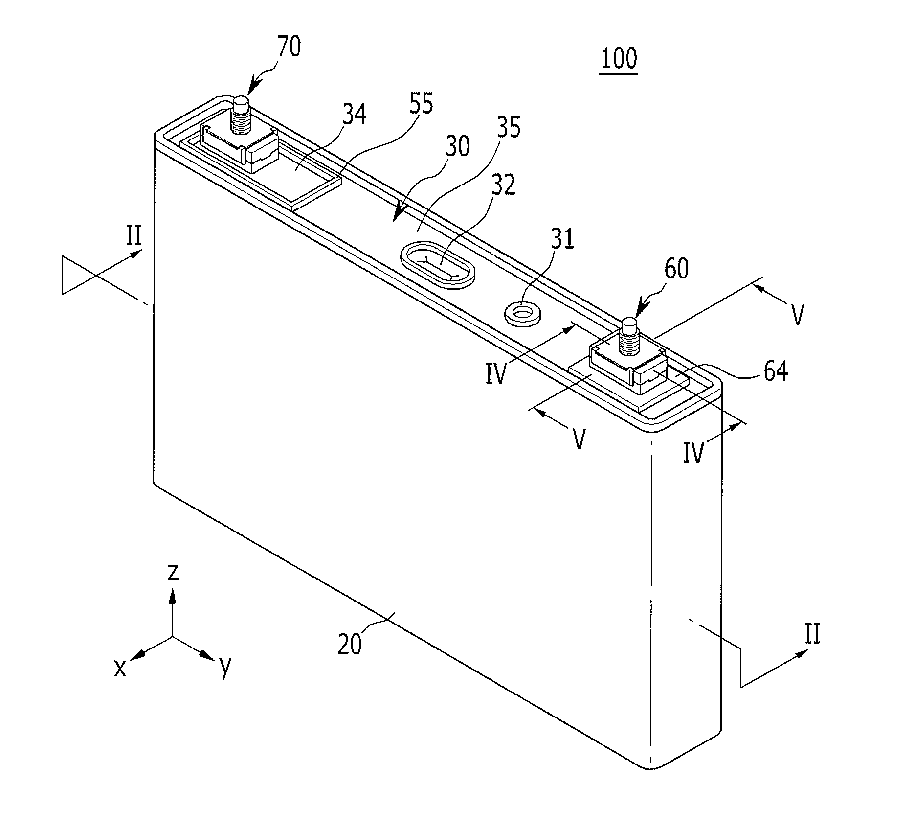
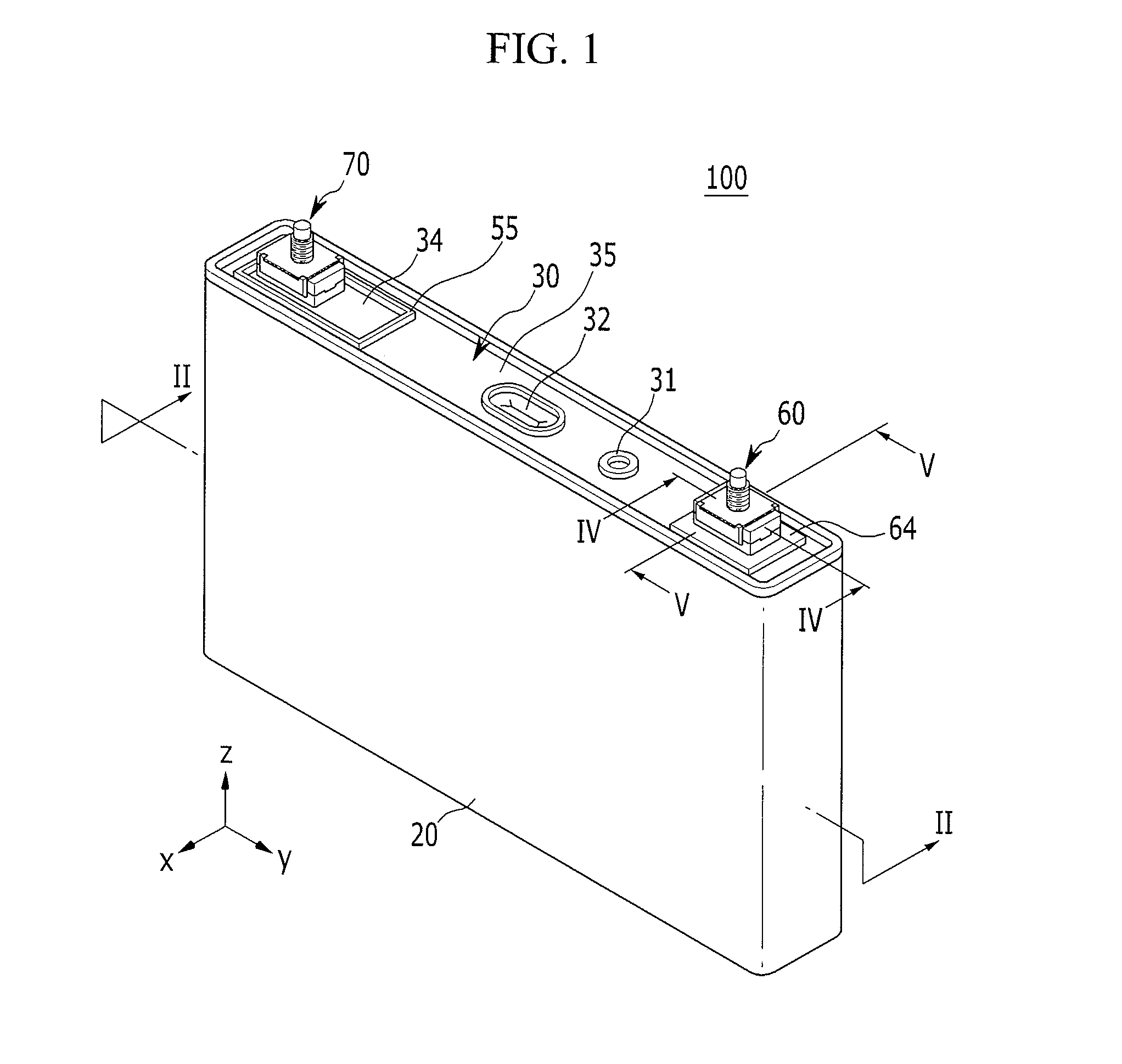
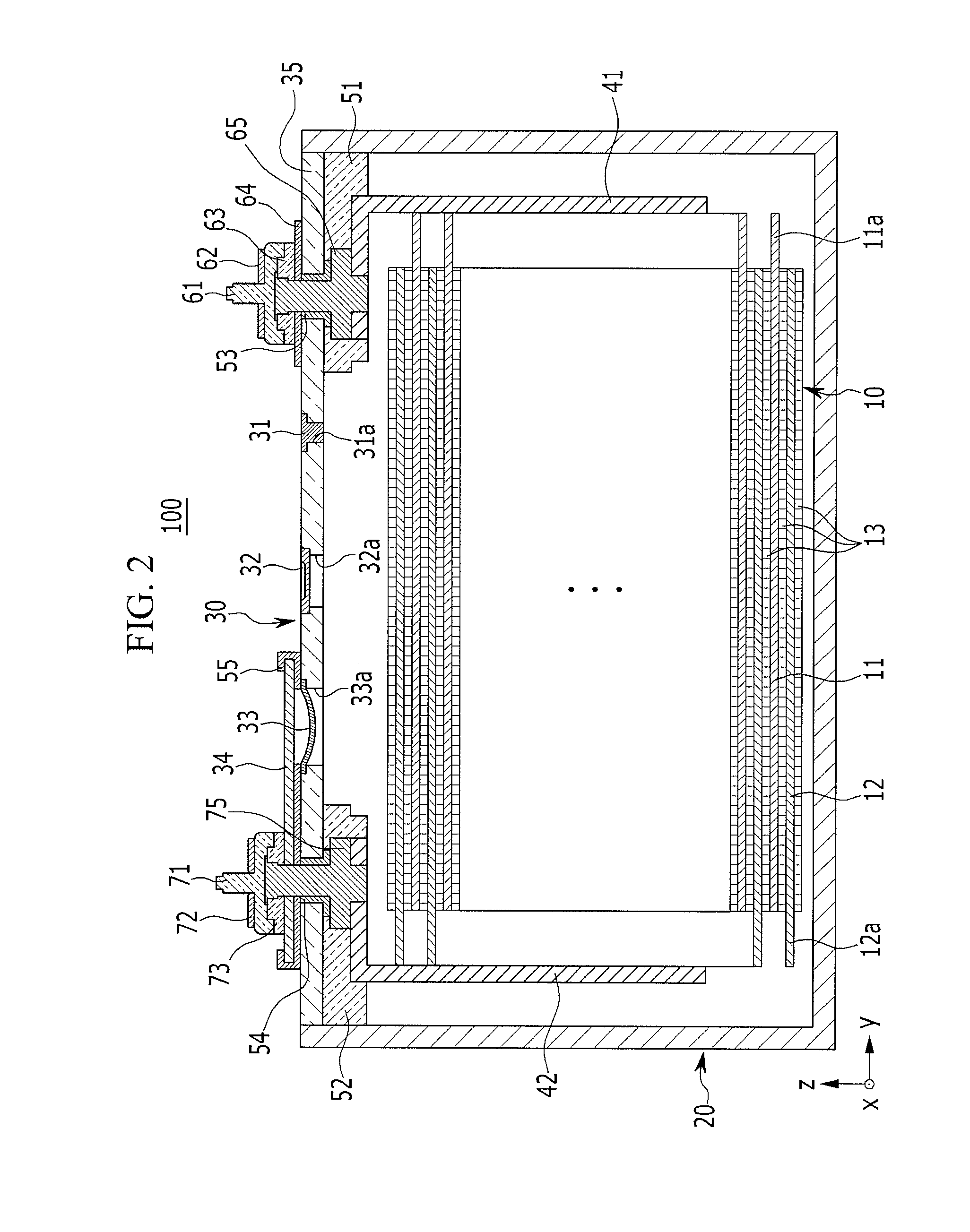
[0034]FIG. 1 is a perspective view illustrating a rechargeable battery according to a first exemplary embodiment of the present invention, and FIG. 2 is a cross-sectional view of the rechargeable battery ...


PUM

PropertyMeasurementUnit
strengthaaaaaaaaaa
electrical conductivityaaaaaaaaaa
electricallyaaaaaaaaaa

Abstract

A rechargeable battery includes an electrode assembly including a positive electrode, a negative electrode, and a separator therebetween; a case that has an opening that houses the electrode assembly; a cap assembly including a cap plate that covers the opening of the case; and an electrode terminal that is electrically connected to the electrode assembly and protrudes through the cap plate to the outside of the case. The electrode terminal includes a lower terminal plate that is connected to the electrode assembly, an upper terminal plate that covers an upper part of the lower terminal plate, and a terminal fastener that is housed in a space between the lower terminal plate and the upper terminal plate that protrudes through an upper surface of the upper terminal plate.

Description

CROSS-REFERENCE TO RELATED APPLICATION[0001]This application claims priority to and the benefit of U.S. Provisional Application No. 61 / 374,059 filed on Aug. 16, 2010, in the United States Patent and Trademark Office, the disclosure of which is incorporated herein in its entirety by reference.BACKGROUND[0002]1. Field[0003]The present invention relates to a rechargeable battery.[0004]2. Description of the Related Art[0005]Unlike a primary battery, a rechargeable battery is designed to be recharged by a charging process that changes external electric energy to a chemical energy form and stores the chemical energy and discharged by a discharging process that changes the chemical energy to an electric energy form for use of the electric energy.[0006]Representative examples of a rechargeable battery include a nickel hydrogen battery, a nickel cadmium battery, a lithium ion battery, and a lithium polymer battery.[0007]In general, a rechargeable battery includes an electrode assembly includ...

Claims


Application Information

Patent Timeline
Patent Type & Authority Applications(United States)
IPC IPC(8): H01M2/06H01M2/02H01M2/24H01M50/176H01M50/505H01M50/509H01M50/529H01M50/55H01M50/557H01M50/562
CPCH01M2/0212H01M2/0426H01M2/06H01M10/0413H01M2/305H01M6/42H01M2/206Y02E60/10H01M50/557H01M50/169Y02P70/50H01M50/562H01M50/509H01M50/55H01M50/505H01M50/176H01M50/531
Inventor KIM, SUNG-BAE
Owner ROBERT BOSCH GMBH
Why Eureka
Try Eureka