
Intervertebral implant device for a posterior interbody fusion surgical procedure

a technology of intervertebral implants and surgical procedures, which is applied in the field of intervertebral implant devices for posterior interbody fusion surgical procedures, can solve the problems of temporary or permanent nerve damage, limited lateral placement of implant devices or cages, and additional refraction of cauda equina and nerve roots

Active Publication Date: 2011-10-06
CTL MEDICAL CORP
View PDF1 Cites 21 Cited by
  • Summary
  • Abstract
  • Description
  • Claims
  • Application Information

AI Technical Summary

Benefits of technology

[0007]In various exemplary embodiments, the present invention provides an intervertebral implant device for a posterior interbody fusion surgical procedure. Advantageously, this intervertebral implant device is configured such that it may be surgically implanted in the spine of a patient through a minimal access window, thereby sparing and preserving the associated facets to the greatest degree possible.

Problems solved by technology

Advantageously, the T-PLIF technique avoids damage to nerve structures, such as the dura, cauda equina, and nerve roots, but the resulting transforaminal window available to remove the affected disc, prepare the vertebral endplates, and insert the implant device or cage is limited laterally by soft tissue and medially by the cauda equina.
However, as these devices and cages are not designed specifically for the T-PLIF procedure, they are not shaped to be easily insertable into the affected disc space through the narrow transforaminal window, and may require additional refraction of the cauda equina and nerve roots.
Such retraction may cause temporary or permanent nerve damage.
In addition, some of these devices and cages, such as the threaded titanium, ceramic, and polymer cages, suffer from the disadvantage of requiring drilling and tapping of the vertebral endplates prior to insertion.
Further, the incidence of subsidence in long term use is not known for such devices and cages.
Finally, the restoration of lordosis, i.e. the natural curvature of the lumbar spine, is very difficult to achieve when a cylindrical or square titanium, ceramic, or polymer cage is used.

Method used


Image

  • Intervertebral implant device for a posterior interbody fusion surgical procedure
  • Intervertebral implant device for a posterior interbody fusion surgical procedure
  • Intervertebral implant device for a posterior interbody fusion surgical procedure

Examples


Embodiment Construction

[0031]In various exemplary embodiments, the present invention provides an intervertebral implant device for a posterior interbody fusion surgical procedure. Advantageously, this intervertebral implant device is configured such that it may be surgically implanted in the spine of a patient through a minimal access window, thereby sparing and preserving the associated facets to the greatest degree possible.

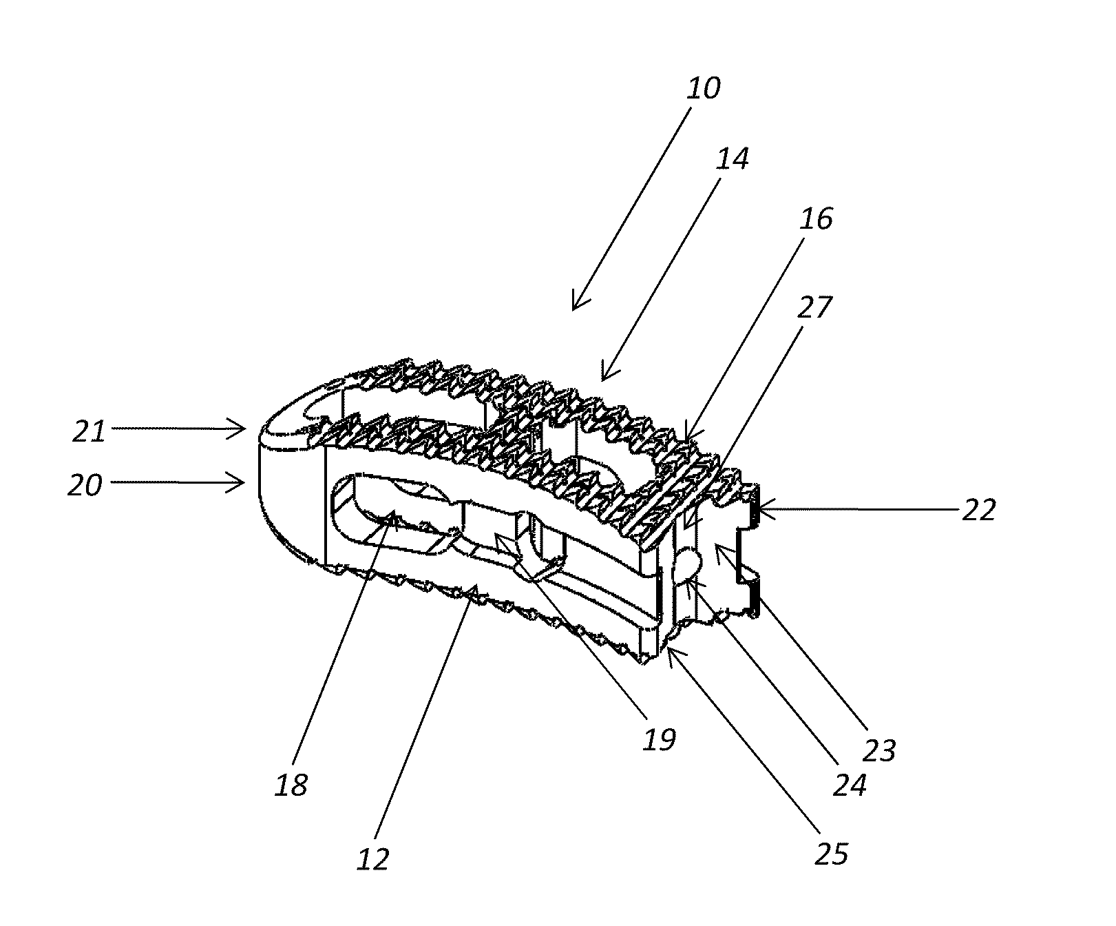
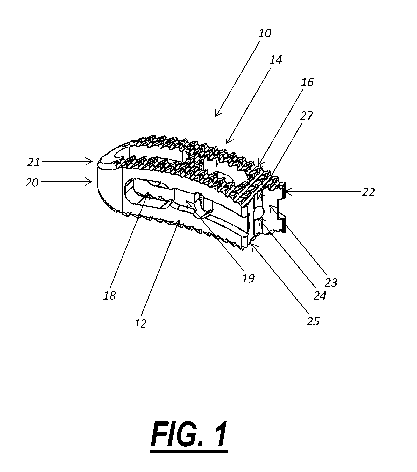
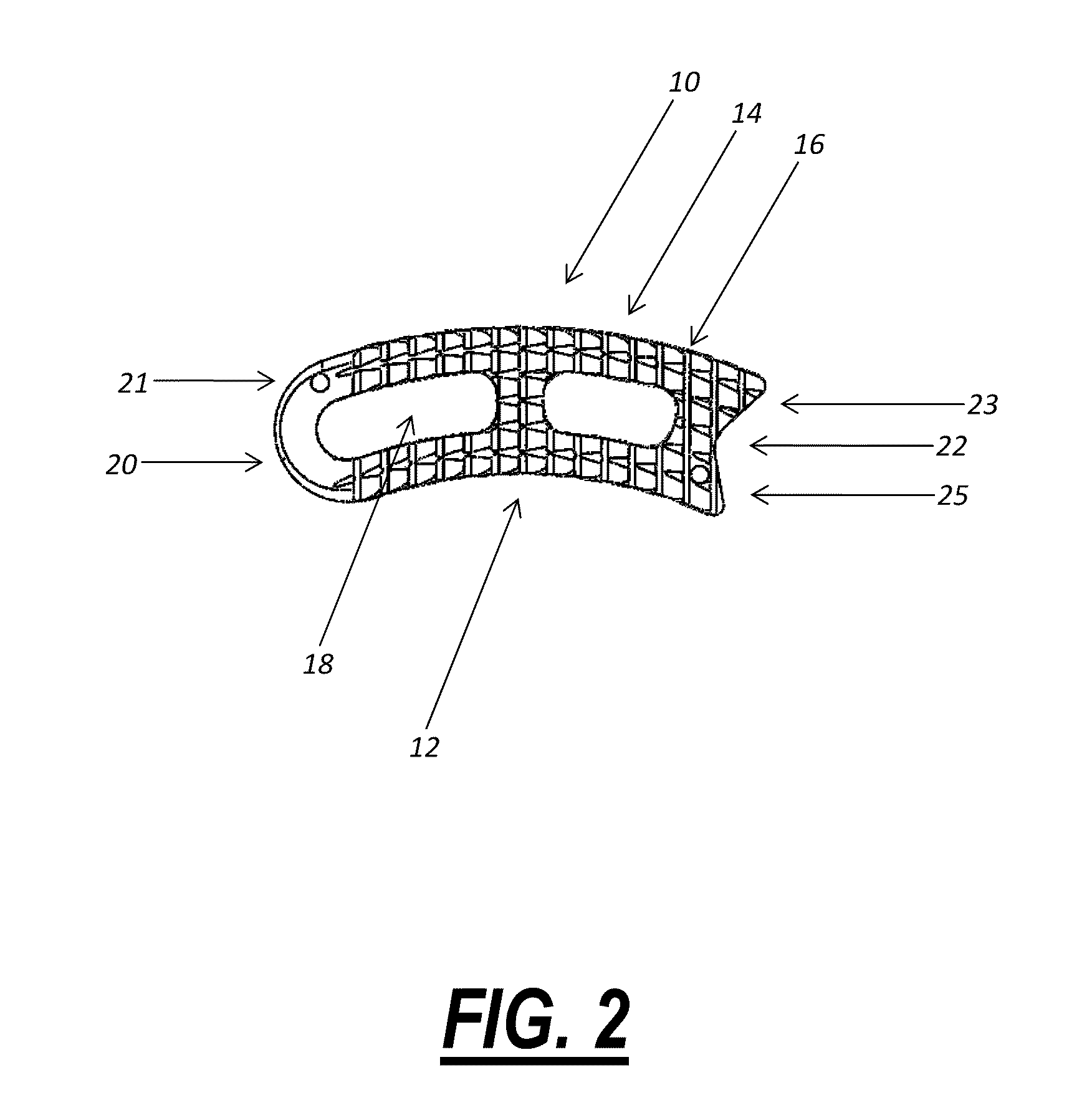
[0032]FIG. 1 is a perspective diagram illustrating one exemplary embodiment of the intervertebral implant device 10 of the present invention. In this exemplary embodiment, the intervertebral implant device 10 includes a pair of substantially parallel opposed arcuate surfaces 12 and a pair of substantially parallel opposed frictional surfaces 14 including a plurality of raised structures 16, such as teeth, grooves or the like. The pair of opposed arcuate surfaces 12 and the pair of opposed frictional surfaces 14 together form a prismatic structure that has a slight curve in one plane....


PUM


Abstract

An intervertebral implant device, including: a pair of substantially parallel opposed arcuate surfaces; a pair of substantially parallel opposed frictional surfaces each including a plurality of raised structures; a substantially curved end wall joining the pair of parallel opposed arcuate surfaces; and a substantially recessed end wall joining the pair of parallel opposed arcuate surfaces; wherein the intervertebral implant device defines one or more voids in which a bone graft material is selectively disposed. Preferably, the substantially recessed end wall is configured to selectively and pivotably receive one or more surgical implantation devices.

Description

CROSS-REFERENCE TO RELATED APPLICATION[0001]The present patent application / patent claims the benefit of priority of U.S. Provisional Patent Application No. 61 / 248,052, filed on Oct. 2, 2009, and entitled “INTERVERTEBRAL IMPLANT DEVICE FOR A POSTERIOR INTERBODY FUSION SURGICAL PROCEDURE,” the contents of which are incorporated in full by reference herein.FIELD OF THE INVENTION[0002]The present invention relates generally to an intervertebral implant device for a posterior interbody fusion surgical procedure. Advantageously, this intervertebral implant device is designed and configured such that it may be surgically implanted in the spine of a patient through a minimal access window, thereby sparing and preserving the associated facets to the greatest degree possible.BACKGROUND OF THE INVENTION[0003]A variety of spinal conditions, such as compression of the spinal cord nerve roots, degenerative disc disease, herniated nucleus pulposus, spinal stenosis, and spondylolisthesis may cause ...

Claims


Application Information

Patent Timeline
Patent Type & Authority Applications(United States)
IPC IPC(8): A61F2/44
CPCA61F2/442A61F2/4465A61F2/4611A61F2002/30779A61F2002/4629A61F2002/30878A61F2002/30892A61F2002/30904A61F2002/4475A61F2002/30785A61F2002/30593
Inventor COBB, JOHNATKINSON, WILLIAMHARRIS, PETER
Owner CTL MEDICAL CORP
Learn More