Driver-airbag-apparatus-attaching structure and steering wheel

Active Publication Date: 2011-10-13
JOYSON SAFETY SYST JAPAN GK
View PDF10 Cites 8 Cited by
  • Summary
  • Abstract
  • Description
  • Claims
  • Application Information

AI Technical Summary

Benefits of technology

[0027]In this case, if the engaging portion of the bracket is provided as a through hole extending through the bracket as in the seventh aspect, the driver airbag apparatus can be easily removed from the steering wheel by inserting the tool into the

Problems solved by technology

Therefore, the mechanism has a complicated configuration.
This may limit the provision of devices such as a damper, a paddle sw

Method used


Image

  • Driver-airbag-apparatus-attaching structure and steering wheel
  • Driver-airbag-apparatus-attaching structure and steering wheel
  • Driver-airbag-apparatus-attaching structure and steering wheel

Examples


Embodiment Construction

[0038]Embodiments of the present invention will now be described with reference to the drawings.

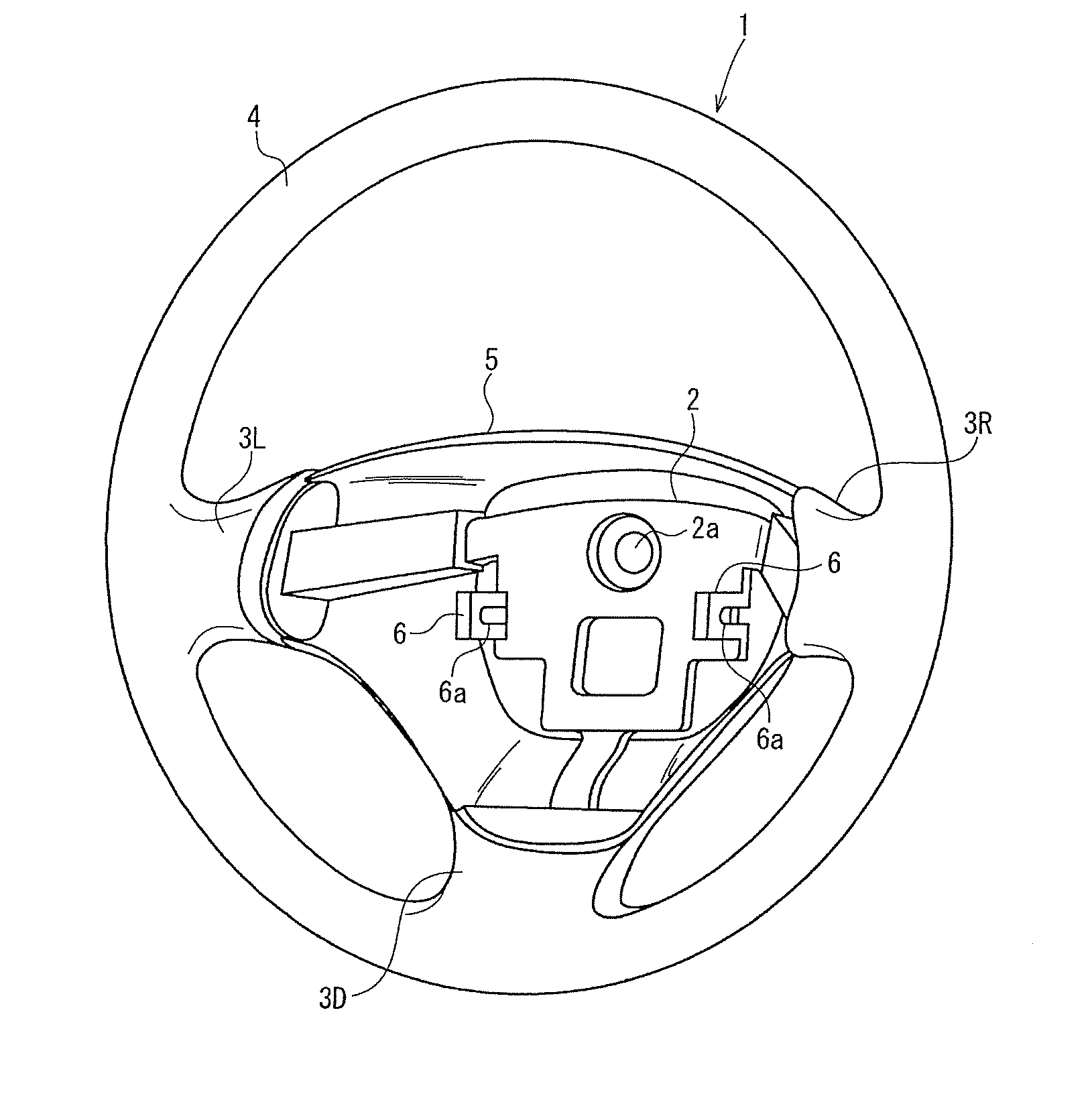
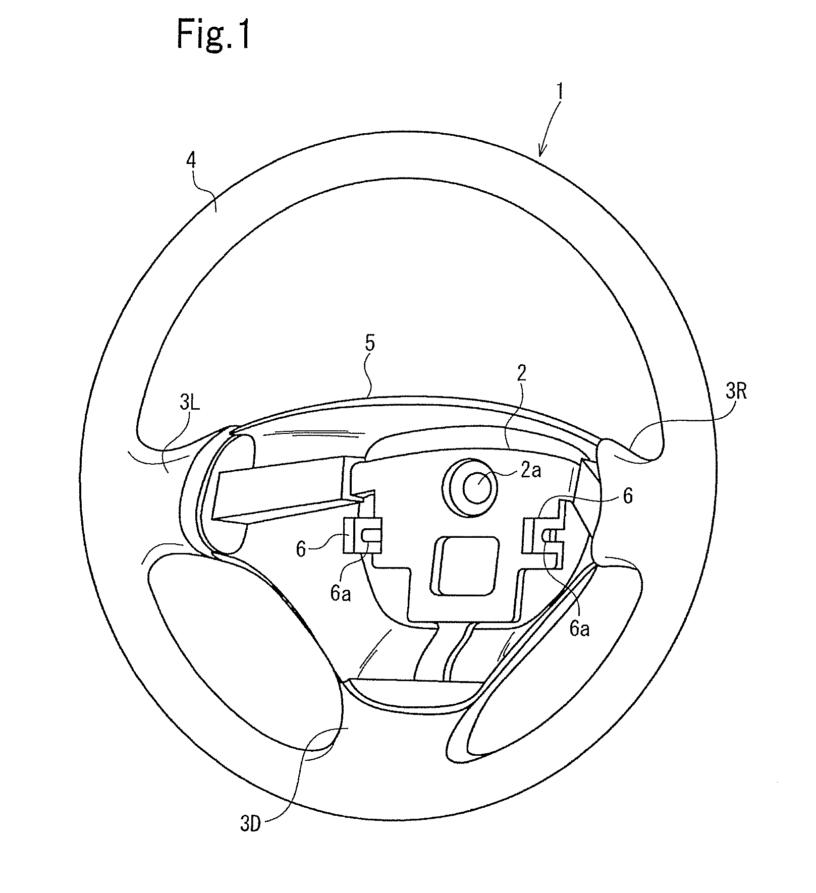
[0039]FIG. 1 is a perspective view of a steering wheel to which a driver airbag apparatus is attached with a driver-airbag-apparatus-attaching structure according to an embodiment. FIG. 2 is a perspective view (exploded view) of a snap-lock mechanism. FIG. 3 is a sectional view of a retainer and a steering hub portion taken along line III-III of FIG. 2. FIG. 4 is a front view (exploded view) of the snap-lock mechanism seen from a side thereof nearer to the outer periphery of the steering wheel. FIGS. 5a to 5c are sectional views illustrating the operation of the snap-lock mechanism. Note that FIG. 5a illustrates a state of the snap-lock mechanism before a projecting portion and an engaging portion engage with each other, FIG. 5b illustrates a state where the projecting portion and the engaging portion are being made to engage with each other, and FIG. 5c illustrates a state after the proj...


PUM


Abstract

A driver-airbag-apparatus-attaching structure is provided having a simple configuration and with which space can be saved. A snap-lock mechanism includes brackets projecting from the front surface of a steering hub portion, attachment pieces projecting from the bottom surface of a retainer of a driver airbag apparatus in such a manner as to overlap the brackets, openings provided in the brackets, and projecting portions projecting from surfaces of the respective attachment pieces that are to face the respective brackets. The projecting portions are continuous with the attachment pieces with respective elastically deformable portions interposed therebetween. When the driver airbag apparatus is bought near to the steering hub portion, the attachment pieces move along the brackets, and the projecting portions receive reactive forces from the brackets, whereby the elastically deformable portions elastically deform. When the projecting portions reach the openings, the elastically deformable portions elastically restore the original forms, and the projecting portions engage with the openings.

Description

TECHNICAL FIELD[0001]The present invention relates to a driver-airbag-apparatus-attaching structure with which a driver airbag apparatus is attached to the front surface of a steering wheel, and particularly to a driver-airbag-apparatus-attaching structure that enables a driver airbag apparatus to be attached to a steering wheel with the aid of a snap-lock mechanism. The present invention also relates to a steering wheel to which a driver airbag apparatus is attached with the driver-airbag-apparatus-attaching structure.BACKGROUND ART[0002]A driver-airbag-apparatus-attaching structure that enables a driver airbag apparatus to be attached to a steering wheel with a single motion with the aid of a snap-lock mechanism is disclosed in Japanese Unexamined Patent Application Publication No. 2002-12117.[0003]In the above publication, a driver airbag apparatus has a plurality of pins projecting toward a steering wheel, and the steering wheel has a plurality of through holes into which the re...

Claims


Application Information

Patent Timeline
IPC IPC(8): B60R21/203B60R21/20B60R21/217B62D1/10
CPCB60R21/2035
Inventor AMAMORI, ICHIROSHIBATA, HIROKI
Owner JOYSON SAFETY SYST JAPAN GK
Why Eureka
Try Eureka