Imaging device, display control method and program

a technology of display control and imaging device, applied in the field of imaging device, can solve the problems of insufficient preparation of the next imaging action and relatively long processing time, and achieve the effect of facilitating identification of the progress situation

Inactive Publication Date: 2011-10-13
SONY CORP
View PDF4 Cites 40 Cited by
  • Summary
  • Abstract
  • Description
  • Claims
  • Application Information

AI Technical Summary

Benefits of technology

[0021]According to the embodiment of the present invention, it is possible to easily identify the p...

Problems solved by technology

Although the plurality of images generated by the imaging actions may be confirmed by performing display after the series of imaging actions is finished, if the number of images to be generated is large, the processing time the...

Method used


Image

  • Imaging device, display control method and program
  • Imaging device, display control method and program
  • Imaging device, display control method and program

Examples


first embodiment

1. First Embodiment

Configuration Example of Imaging Device

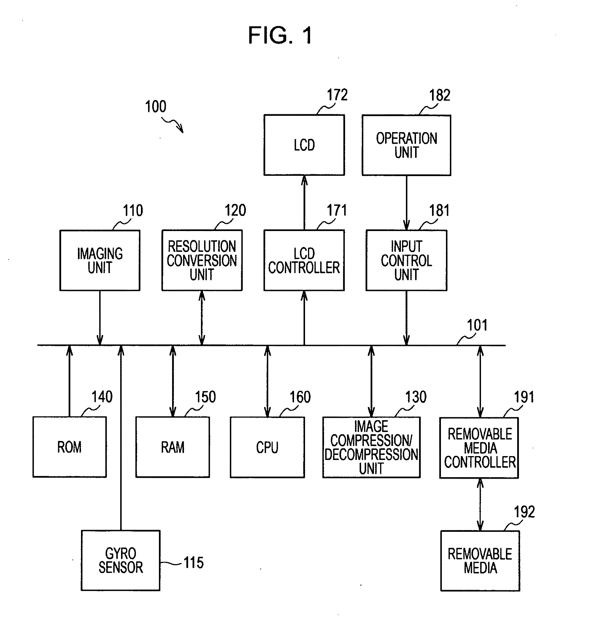
[0060]FIG. 1 is a block diagram showing an internal configuration example of an imaging device 100 according to a first embodiment of the present invention. The imaging device 100 includes an imaging unit 110, a gyro sensor 115, a resolution conversion unit 120, and an image compression / decompression unit 130. The imaging device 100 includes a Read Only Memory (ROM) 140, a Random Access Memory (RAM) 150, and a Central Processing Unit (CPU) 160. The imaging device 100 includes a Liquid Crystal Display (LCD) controller 171, an LCD 172, an input control unit 181, an operation unit 182, a removable media controller 191, and a removable medium 192. Exchange performed between the units configuring the imaging device 100 is performed through a bus 101. The imaging device 100 may be, for example, realized by a digital camera for capturing a subject, generating plural pieces of image data (captured images), and performing various imag...

second embodiment

2. Second Embodiment

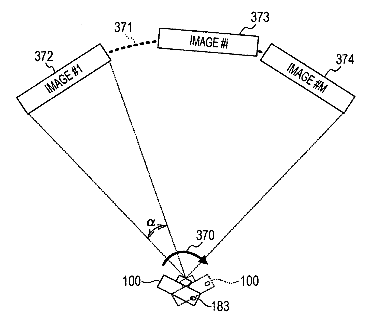
[0217]In the first embodiment of the present invention, the example of displaying the plurality of image generated by the series of imaging actions based on the predetermined rule is described. In the case of confirming the multi-viewpoint images generated by the imaging actions after the imaging actions of the multi-viewpoint images of the multi-viewpoint image photographing mode are finished, the user may wish to display a multi-viewpoint image of a specific viewpoint. Therefore, in the second embodiment of the present invention, an example of changing and displaying an image as an object to be displayed according to the attitude of the imaging device after the imaging actions of the multi-viewpoint images are finished will be described. The configuration of the imaging device of the second embodiment of the present invention is substantially equal to that of the examples shown in FIGS. 1 and 11 except that an input / output panel 710 is provided instead of the L...


PUM


Abstract

An imaging device includes an image unit that captures a subject and generates a plurality of consecutive captured images in time series, a synthesis unit that performs synthesis using at least a part of each of the plurality of generated captured images and generates a plurality of synthesized images having an order relationship based on a predetermined rule, and a control unit which performs control for displaying information about the progress of the generation of the synthesized images by the synthesis unit on a display unit as progress information, after the process of generating the plurality of captured images by the imaging unit is finished.

Description

BACKGROUND OF THE INVENTION[0001]1. Field of the Invention[0002]The present invention relates to an imaging device and, more particularly, to an imaging device for displaying an image, a display control method, and a program for executing the method on a computer.[0003]2. Description of the Related Art[0004]Recently, imaging devices for capturing a subject, such as a person or an animal, so as to generate image data and recording the image data as image content, such as a digital camera or a digital video camera (for example, a camcorder), have come into wide use. An imaging device for displaying an image to be recorded on a display unit when an imaging action is finished so as to confirm image content is being proposed (a so-called review display).[0005]An imaging device for generating a plurality of images by a series of imaging actions and recording the plurality of generated images in association with each other exists. For example, there is an imaging device for recording a plu...

Claims


Application Information

Patent Timeline
IPC IPC(8): H04N5/228H04N5/76G03B7/08G03B37/00H04N5/225H04N5/232H04N101/00
CPCH04N5/23238H04N5/272H04N5/23293H04N23/698H04N23/63
Inventor ISHIDA, YOSHIHIRO
Owner SONY CORP
Why Eureka
Try Eureka