Display of aec sensor location

a technology of aec sensor and location, applied in the field of radiographic imaging, can solve the problems of less accurate detection of exposure level, risk of over- or under-exposure, and some problems

Active Publication Date: 2011-10-13
CARESTREAM HEALTH INC
View PDF8 Cites 33 Cited by
  • Summary
  • Abstract
  • Description
  • Claims
  • Application Information

AI Technical Summary

Benefits of technology

[0015]An object of the present invention is to address the need for improvement in how AEC sensor elements are used in diagnostic imaging applications. Advantageously, methods and apparatus of the present invention visually indicate the relative position of AEC sensors, so that sensor elements can be positioned appropriately for obtaining an image of a subject in an x-ray exam.

Problems solved by technology

The use of a standard pattern of AEC sensor elements 22 in fixed positions, as shown in FIG. 1B can present some problems.
However, this solution can mean less accurate detection of the exposure level and risks over- or under-exposure for obtaining the image of the patient or other subject.
One problem with conventional AEC apparatus relates to the guesswork that is needed in order to obtain proper positioning of AEC sensor elements relative to the subject and to the imaging detector.

Method used


Image

  • Display of aec sensor location
  • Display of aec sensor location
  • Display of aec sensor location

Examples


Embodiment Construction

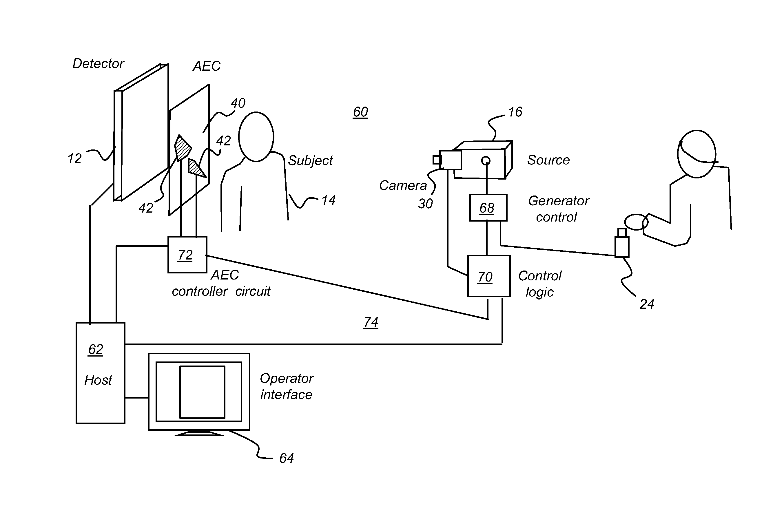
[0040]The following is a detailed description of the preferred embodiments of the invention, reference being made to the drawings in which the same reference numerals identify the same elements of structure in each of the several figures.

[0041]In the context of the present disclosure, the use of terms such as “first”, “second”, “third”, etc., does not by itself connote any priority, precedence, or order of a component or claim element over another or the temporal order in which acts of a method are performed. These terms may be used more generally as labels to distinguish one element having a certain name from another element having the same name (but for use of the ordinal term) or to distinguish the claim elements.

[0042]The term “set”, as used herein, refers to a non-empty set, as the concept of a collection of elements or members of a set is widely understood in elementary mathematics. The term “subset”, unless otherwise explicitly stated, is used herein to refer to a non-empty p...


PUM


Abstract

A method for indicating a position of a radiation energy sensor element in a radiographic imaging system, the method executed at least in part by a computer, identifies the position of the radiation energy sensor element relative to a subject to be imaged and displays the identified position relative to the subject.

Description

CROSS REFERENCE TO RELATED APPLICATION[0001]This application claims priority to U.S. Provisional Application Ser. No. 61 / 323,476, filed 13 Apr. 2010, entitled “MOBILE UNIT HAVING TUBE ALIGNMENT SYSTEM,” by Lalena, incorporated herein by reference.[0002]This application claims priority to Provisional Application Ser. No. 61 / 449,932, filed 7 Mar. 2011, entitled “GRAPHIC USER INTERFACE FOR MOBILE UNIT,” by Stagnitto, incorporated herein by reference.[0003]The present application relates to patent application U.S. Ser. No. ______ entitled “CONFIGURABLE AEC SENSOR FOR AN X-RAY SYSTEM” in the name of Lalena, filed on even date.[0004]The present application relates to patent application U.S. Ser. No. ______ entitled “EXPOSURE CONTROL USING DIGITAL RADIOGRAPHY DETECTOR” in the name Wang, filed on even date.FIELD OF THE INVENTION[0005]The invention relates generally to the field of radiographic imaging and more particularly relates to apparatus and methods for control of exposure energy in a...

Claims


Application Information

Patent Timeline
Patent Type & Authority Applications(United States)
IPC IPC(8): H05G1/42H05G1/64A61B6/08
CPCA61B6/08A61B6/4208A61B6/4266A61B6/587A61B6/542A61B6/4405A61B6/547A61B6/461
Inventor LALENA, MICHAEL C.WANG, XIAOHUIFOOS, DAVID H.
Owner CARESTREAM HEALTH INC
Why Eureka
Try Eureka