Electrical connector and electrical connector assembly with improved contact structures

a technology of contact structure and electrical connector, which is applied in the direction of coupling contact member, connection contact member material, coupling device connection, etc., can solve the problems of easy polluting or damage of contact ends, easy contact of contact ends when in improper use status, and easy generation of electric shock phenomena. , to achieve the effect of improving protection and reliable power transmission

Inactive Publication Date: 2011-10-13
ALLTOP ELECTRONICS SU ZHOU
View PDF57 Cites 14 Cited by
  • Summary
  • Abstract
  • Description
  • Claims
  • Application Information

AI Technical Summary

Benefits of technology

[0008]Accordingly, an object of the present invention is to provide an electrical connector with improved protection means for providing reliable power transmission.
[0009]Another object of the present invention is to provide an electrical connector assembly with improved protection means for providing reliable power transmission.

Problems solved by technology

Since the slice-shape plug contacts are exposed into the receiving cavity directly without any protection to contacting ends thereof, the contacting ends are prone to be contacted when in improper use status.
Therefore, electric shock phenomenon has great possibility to be generated and the contacting ends are easy to be polluted or damaged.
It is more serious when the connectors are used for high-power, high-voltage situations.
However, the retainer is of one-piece structure and needs to align with all the contacting portions of the contacts before assembled to the insulative housing which adds the difficulty of assembly.
The uncovered parts of the contacting portions of the contacts are still very close to the outside and easy to be polluted or damaged.
Also, the one-piece structure has relative slim figure and insufficient strength which is not good enough.
Further, when one contact is out of use, the whole retainer needs to be removed for repair which is not convenient enough.

Method used


Image

  • Electrical connector and electrical connector assembly with improved contact structures
  • Electrical connector and electrical connector assembly with improved contact structures
  • Electrical connector and electrical connector assembly with improved contact structures

Examples


first embodiment

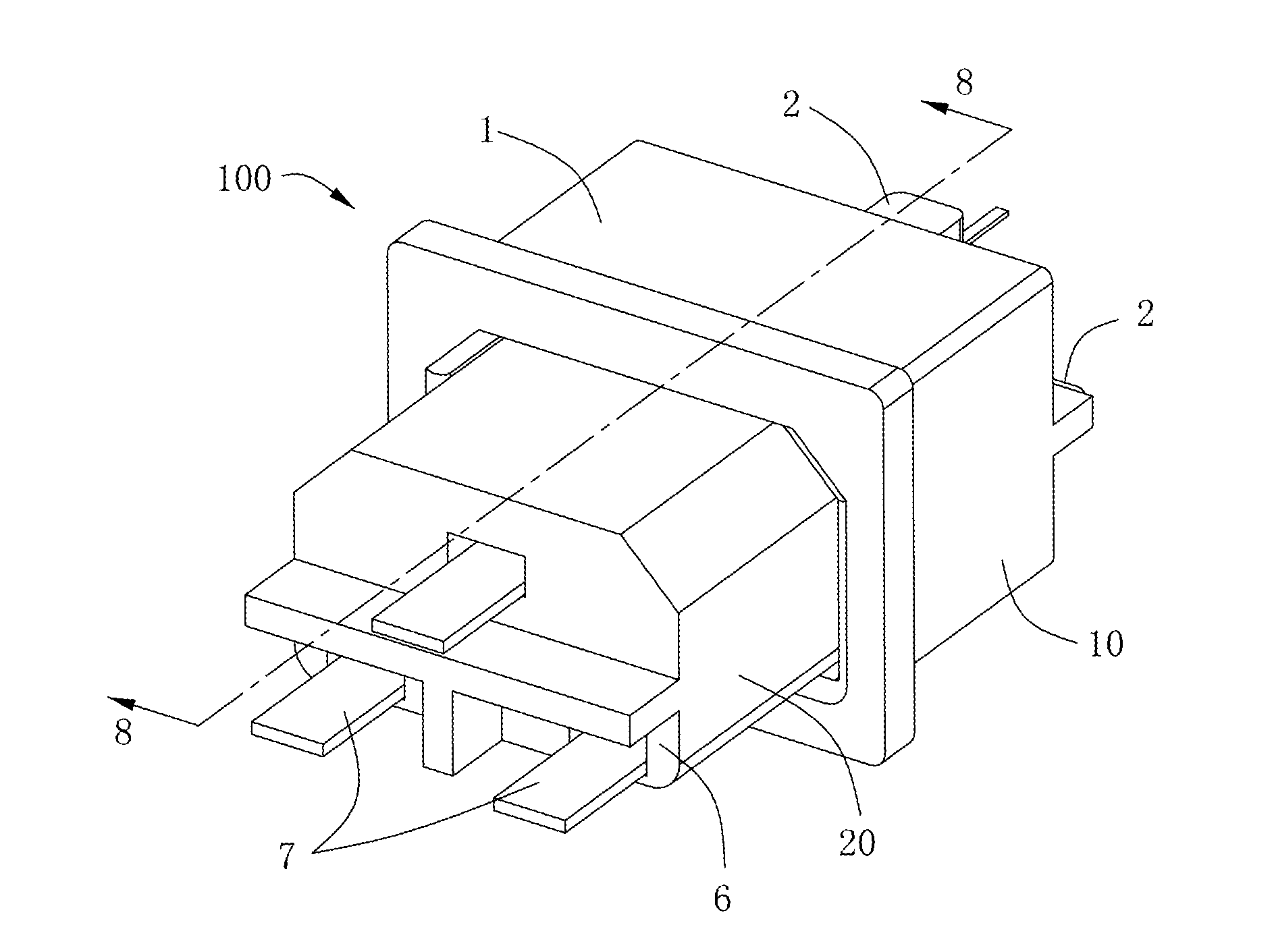
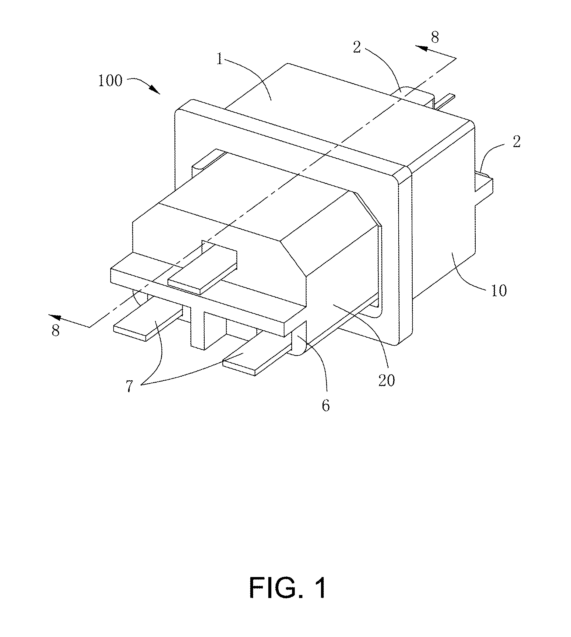
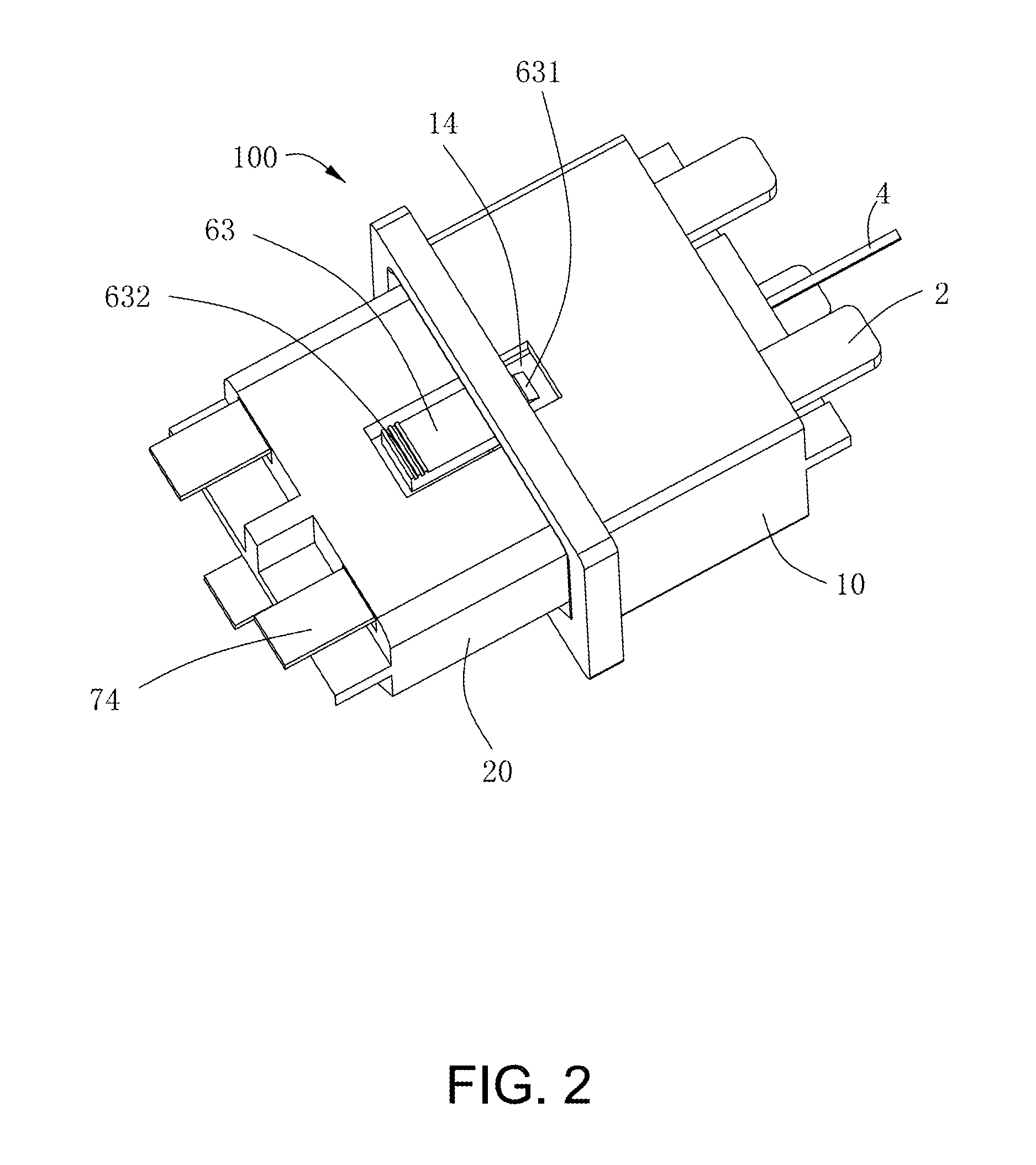
[0033]Referring to FIGS. 1-4, an electrical connector assembly 100 in accordance with the present invention comprises a plug connector 10 and a receptacle connector 20 mating with each other. The plug connector 10 and the receptacle connector 20 are power connectors for power transmission in the preferred embodiment of the present invention, but the connectors are not only restricted to power type connectors. Also, the plug connector 10 and the receptacle connector 20 are the electrical connectors in accordance with the present invention.

[0034]In the first embodiment of the present invention, the plug connector 10 comprises a first insulative housing 1, a plurality of first contacts 2 attached to the first insulative housing 1, and an additional grounding contact 4 also attached to the first insulative housing 1. The receptacle connector 20 comprises a second insulative housing 6 and a plurality of second contacts 7 attached to the second insulative housing 6. The first contacts 2 a...

second embodiment

[0048]Since the plug connector 10, 10′ and the receptacle connector 20, 20′ are high-power power connectors, heat radiation issue must be considered. In the present invention, heat-radiation structures are designed. The first insulative housing 1′ defines a plurality of heat-radiating holes 17′ to communicate with at least one first contact-receiving passageway 121′, while, the second insulative housing 6′ defines a plurality of heat-radiating holes 67′ to communicate with at least one second contact-receiving passageway 60′. In addition, the second retainer 9′ also defines a plurality of heat-radiating passages 97′ to communicate with at least one second contact-receiving passageway 60′. These heat-radiating structures 17′, 67′ and 97′ communicate the first and second contact-receiving passageways 121′, 60′ with outside to radiate heat generated by mated first and second contacts 2′, 7′ to the outside in time to satisfy the heat-radiating requirement.


PUM


Abstract

An electrical connector includes an insulative housing, at least one contact and at least one protecting insulator. The insulative housing defines a mating direction, a mating face and a receiving cavity recessed from the mating face along said mating direction. The at least one contact is received in the insulative housing and includes a contacting portion exposed into the receiving cavity, a retaining portion extending from one end of the contacting portion to be interferentially received in the insulative housing, and a forward end extending from the other end of the contacting portion to locate more closely to the mating face of the insulative housing than the contacting portion, and a connecting portion extending from the retaining portion to be exposed beyond the insulative housing. The protecting insulator entirely covers the forward end of the at least one contact.

Description

BACKGROUND OF THE INVENTION[0001]1. Field of the Invention[0002]The present invention relates to an electrical connector and an electrical connector assembly, more particularly to an electrical connector and an electrical connector assembly for power transmission.[0003]2. Description of Related Art[0004]Electrical connectors are widely used today. In general, electrical connectors can be classified into personal use and industrial use. When in personal use, electrical connectors can be classified as desktop connectors, laptop connectors, mobile phone connectors, consuming connectors, and other types. When in industrial use, electrical connectors can be used in industrial computers, servers, and workstations. Power connector is one common kind of electrical connector used in different equipments. Usually, a plug-type power connector and a receptacle-type power connector mate with each other to supply power to the equipments. Contacts of the plug connector and the receptacle connector...

Claims


Application Information

Patent Timeline
Patent Type & Authority Applications(United States)
IPC IPC(8): H01R13/652H01R24/00
CPCH01R13/44H01R13/64H01R2103/00H01R24/70H01R24/22
Inventor WANG, CHIN-LISHEN, YA-HUI
Owner ALLTOP ELECTRONICS SU ZHOU
Why Eureka
Try Eureka