
Programmable inertial igniters for gun-fired munitions, thermal batteries and the like

a technology of inertial igniter and thermal battery, which is applied in the field of program, can solve the problems of high labor intensity of thermal battery manufacturing process, high cost, and high labor intensity of battery operation, and achieve the effect of low cos

Active Publication Date: 2011-10-20
OMNITEK PARTNERS LLC
View PDF1 Cites 10 Cited by
  • Summary
  • Abstract
  • Description
  • Claims
  • Application Information

AI Technical Summary

Benefits of technology

[0010]A need therefore exists for the development of a novel method and resulting inertial igniters for thermal batteries used in gun fired munitions, particularly for small and low power thermal batteries that could be used in fuzing and other similar applications that occupy small volumes, eliminate the need for external power sources, and can be “programmed” to satisfy various all-fire acceleration requirements, and therefore make it possible to provide low cost inertial igniter solutions for the varieties of gun-fired munitions and other similar applications.

Problems solved by technology

The electrolyte is dry, solid and non-conductive, thereby leaving the battery in a non-operational and inert condition.
The process of manufacturing thermal batteries is highly labor intensive and requires relatively expensive facilities.
Fabrication usually involves costly batch processes, including pressing electrodes and electrolytes into rigid wafers, and assembling batteries by hand.
Such electrical igniters, however, require electrical energy, thereby requiring an onboard battery or other power sources with related shelf life and / or complexity and volume requirements to operate and initiate the thermal battery.
However, the existing inertial igniters are relatively large and not suitable for small and low power thermal batteries, particularly those that are being developed for use in miniaturized fuzing, future smart munitions, and other similar applications.

Method used


Image

  • Programmable inertial igniters for gun-fired munitions, thermal batteries and the like
  • Programmable inertial igniters for gun-fired munitions, thermal batteries and the like
  • Programmable inertial igniters for gun-fired munitions, thermal batteries and the like

Examples


Embodiment Construction

[0028]The safety mechanism can be a purely mechanical mechanism, which responds to acceleration applied to the inertial igniter. If the applied acceleration reaches or passes the designed initiation levels and if its duration is long enough, i.e., larger than any expected to be experienced as the result of accidental drops or explosions in their vicinity or other non-firing events, i.e., if the resulting impulse levels are lower than those indicating gun-firing, then the mechanism should return to its original pre-acceleration configuration, and the pyrotechnics component of the igniter is not initiated. Otherwise, the initiation system is released to provide ignition of the pyrotechnics. For example, the design requirements for actuation for one application are summarized as:

[0029]1. The device must fire when given a [square] pulse acceleration of 900 G±150 G for 15 ms in the setback direction.

[0030]2. The device must not fire when given a [square] pulse acceleration of 2000 G for ...


PUM


Abstract

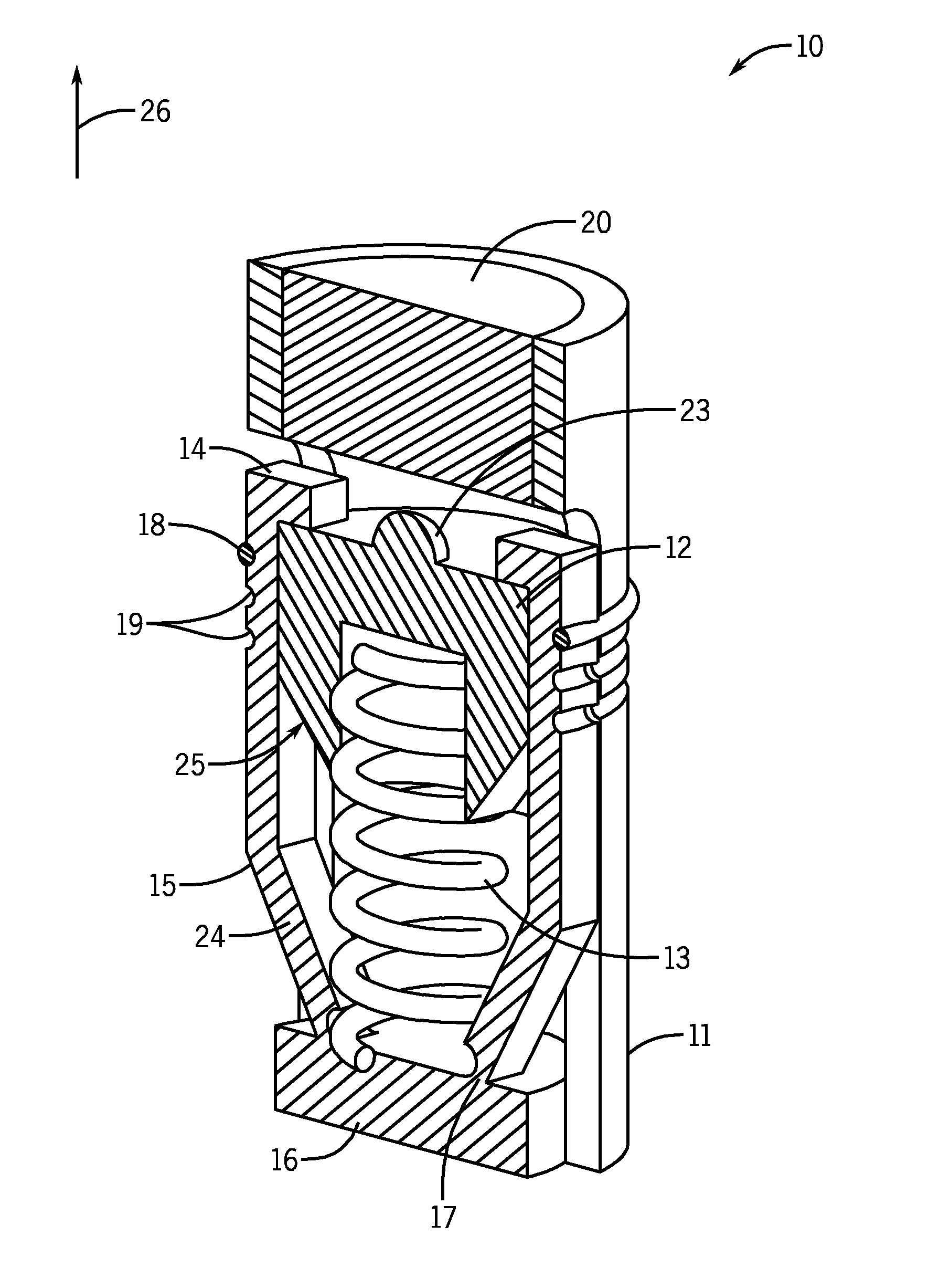
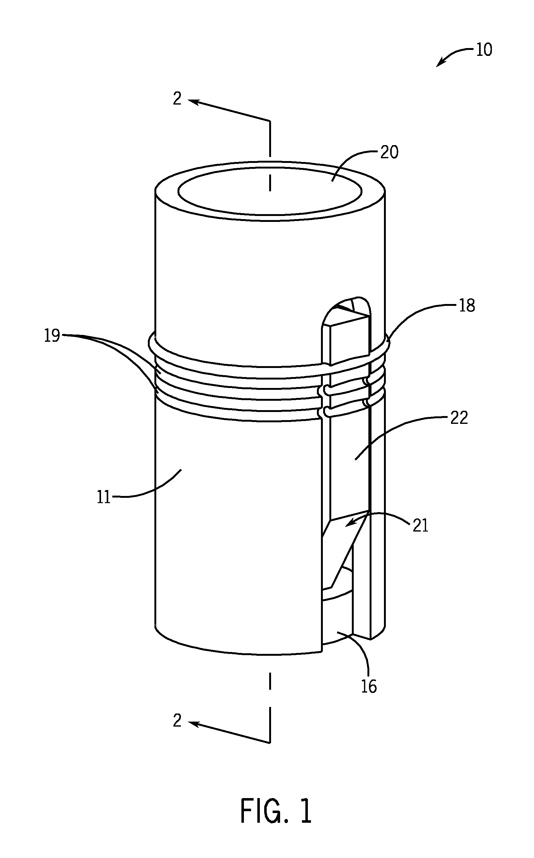
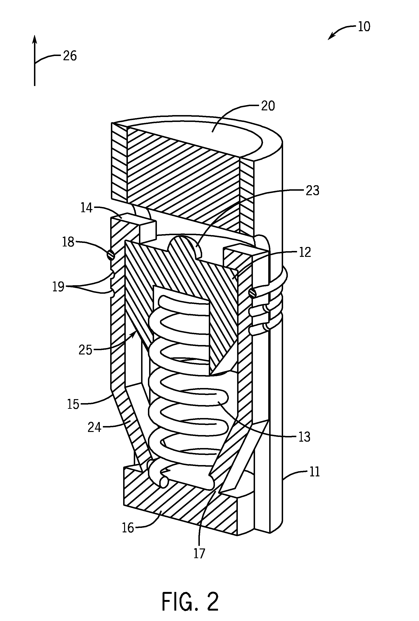
An inertial igniter including: a housing; a striker mass movable relative to the housing; a biasing element for biasing the striker mass towards a percussion primer; one or more movable members each having one or more stops, the one or more stops having a first position for preventing a portion of the striker mass from striking the percussion primer and a second position allowing the portion of the striker mass to strike the percussion primer; wherein the movable members move the one or more stops to the second position when subjected to a predetermined acceleration profile.

Description

BACKGROUND[0001]1. Field of the Invention[0002]The present invention relates generally to acceleration (deceleration) operated inertial igniters for use in gun-fired munitions, and more particularly for inertial igniters for thermal batteries used in gun-fired munitions and other similar applications that are readily programmed to initiate at a desired acceleration level.[0003]2. Prior Art[0004]Thermal batteries represent a class of reserve batteries that operate at high temperatures. Unlike liquid reserve batteries, in thermal batteries the electrolyte is already in the cells and therefore does not require a distribution mechanism such as spinning. The electrolyte is dry, solid and non-conductive, thereby leaving the battery in a non-operational and inert condition. These batteries incorporate pyrotechnic heat sources to melt the electrolyte just prior to use in order to make them electrically conductive and thereby making the battery active. The most common internal pyrotechnic is...

Claims


Application Information

Patent Timeline
Patent Type & Authority Applications(United States)
IPC IPC(8): F42C19/14F42C19/08
CPCF42C7/12F42C15/24F42C15/22F42C15/20
Inventor MURRAY, RICHARD T.RASTEGAR, JAHANGIR S.SPINELLI, THOMAS
Owner OMNITEK PARTNERS LLC
Learn More