
Assisting mechanism of movable body

a technology of assisting mechanism and movable body, which is applied in the direction of mechanical equipment, wing accessories, carpet fasteners, etc., can solve the problems of difficulty in applying a sufficient damping force to the forward movement of the door, limit the amount of rotation of the catcher to assist the forward, etc., to achieve the effect of reducing the range (stroke), reducing the width of the catcher, and reducing the space for the catcher to move forward

Inactive Publication Date: 2011-10-20
NIFCO INC
View PDF13 Cites 25 Cited by
  • Summary
  • Abstract
  • Description
  • Claims
  • Application Information

AI Technical Summary

Benefits of technology

[0032]The assisting mechanism according to this invention can be constituted having a width as small as possible. Also, in the assisting mechanism according to this invention, the width can be made as small as possible without reducing the range (stroke) for assisting the forward movement of the movable body from a prescribed position. That is, because the forward movement of the catcher constituting such assisting mechanism after catching the striker becomes sliding movement from mid-course, the space for the forward movement of the catcher can be made smaller compared to the case when such forward movement of the catcher is entirely dependent on rotation, and the width of the assisting mechanism in the direction orthogonal to the direction of such sliding movement can be made as small as possible.

Problems solved by technology

However, for example, in the case when an apparatus main body supporting the catcher is provided on the door frame of such door, there is a requirement to make the width of the apparatus main body as small as possible because there is a limitation as to the width of the door frame in the direction of forward movement, that is, the front-to-back direction, of the door, and accordingly there is a limitation as to how much the amount of rotation of the catcher can be increased to assist the forward movement of the door over a wider range.
However, it is difficult to ensure a great amount of plunging by only having the piston rod plunged by the rotation of the catcher, and therefore it may be difficult to apply a sufficient damping force to the forward movement of the door.

Method used


Image

  • Assisting mechanism of movable body
  • Assisting mechanism of movable body
  • Assisting mechanism of movable body

Examples


Embodiment Construction

[0044]A typical mode of the embodiment of this invention is described below based on FIG. 1 to FIG. 11.

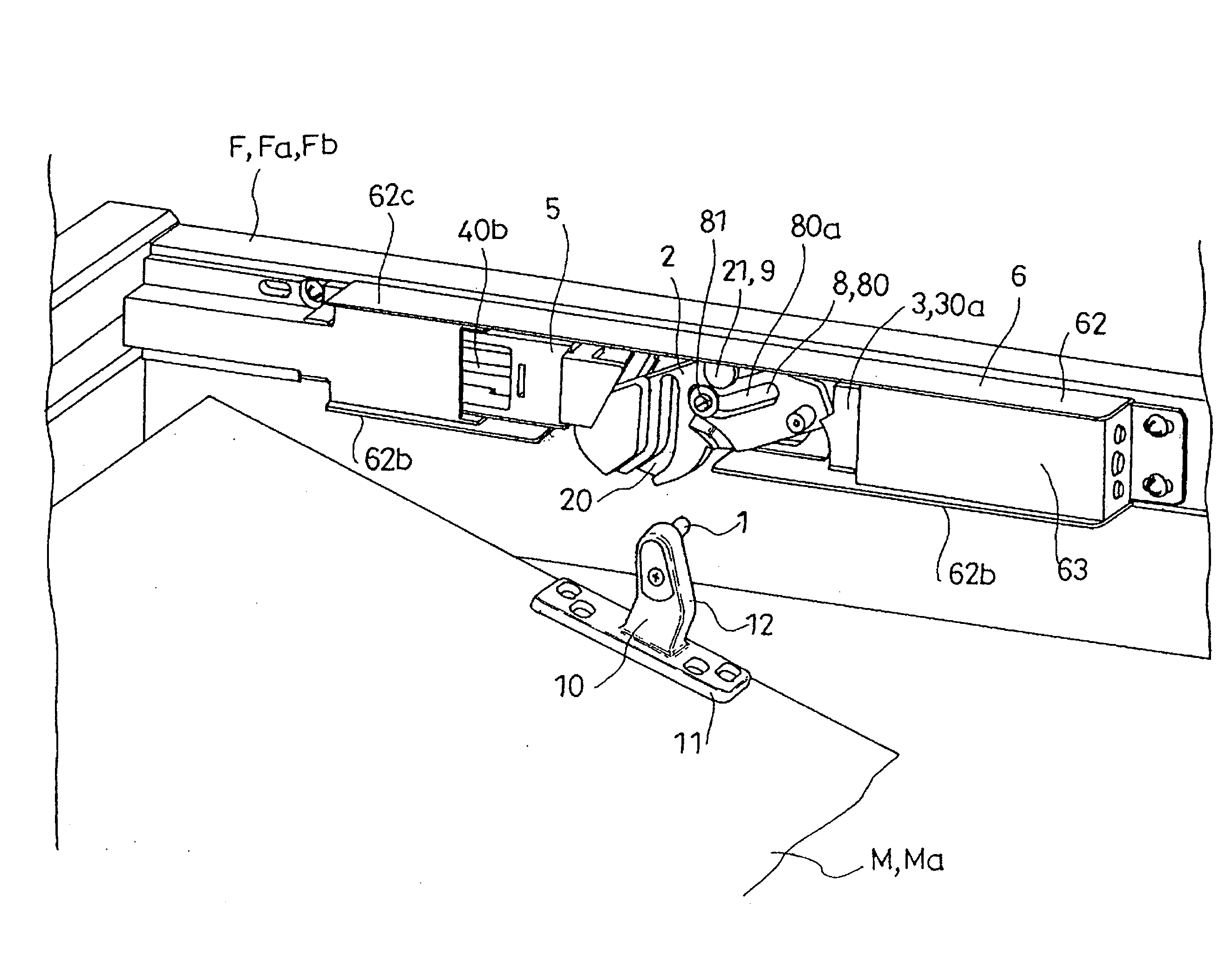
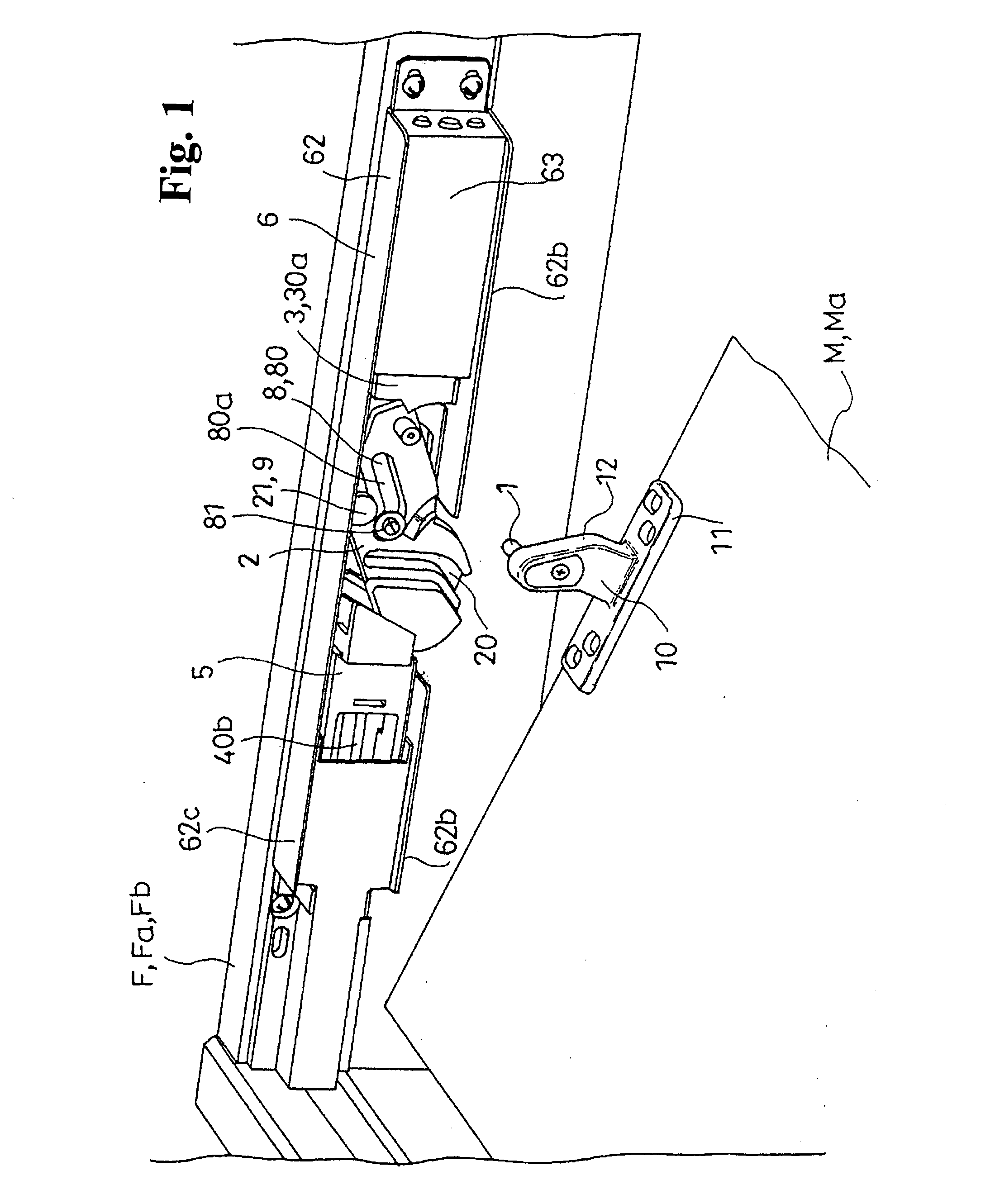
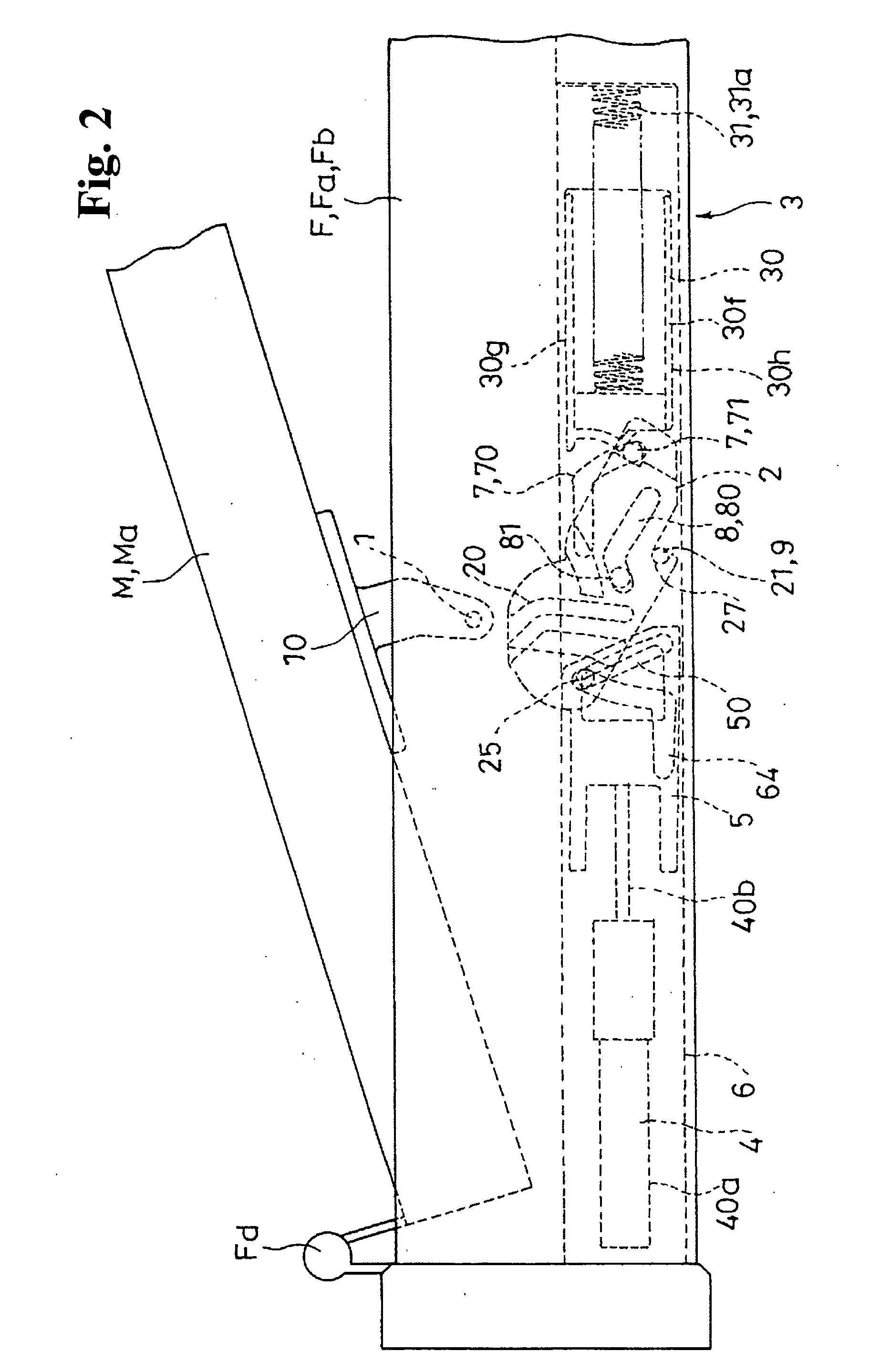
[0045]Here, FIG. 1 illustrates an example in which a catcher 2 constituting an assisting mechanism according to the mode of the embodiment is provided on a door frame Fa as a main body F, and a striker 1 is provided on a door Ma as a movable body M, in the condition seen from below. Also, FIG. 2 illustrates the condition of FIG. 1 seen from above.

[0046]FIG. 3 to FIG. 8 respectively illustrate the aforementioned assisting mechanism seen from below, FIG. 2 illustrates the condition when the catcher 2 is in a standby position, and FIG. 8 illustrates the condition when the catcher 2 is in a final position. When closing the door Ma, that is, when rotating the movable body M toward a reference position, the striker 1 strikes the catcher 2 in the standby position (FIG. 4), and the catcher 2, while catching same, is moved forward up to the final position in the sequence in FIG. 5, FIG. 6, ...


PUM


Abstract

A catcher is supported on a base to be capable of reciprocal movement between a standby position where a striker can be caught or released and a final position, and moves slidingly toward the final position after rotating at a fixed angle from the standby position during forward movement from the standby position. Holding of the state in which the catcher is in the standby position, and the aforementioned sliding movement, are accomplished by urging of an urging device provided on the base. The aforementioned holding is released and forward rotation of the catcher is started when the striker is caught by the catcher in the standby position by forward movement of a movable body, and this forward movement is assisted by the aforementioned urging from mid-course of this forward movement.

Description

TECHNOLOGICAL FIELD[0001]This invention relates to a mechanism that is activated when a movable body, being combined on a main body to be capable of deployment from a reference position and to be capable of reciprocal movement, is operated to move forward from the deployment position up to a prescribed position toward the reference position, to thereby assist the forward movement of the movable body to the reference position.BACKGROUND TECHNOLOGY[0002]There is a withdrawing mechanism, provided with a catcher on a door frame, for catching a striker, provided on a door, in a prescribed position when the door is operated to rotate toward a closed position. Such catcher is provided so as to rotate reciprocally between a standby position and a withdrawn position, and is forcibly rotated by force of a spring from the prescribed position of rotation up to the withdrawn position, thereby to assist the forward movement of the door toward the closed position. (See patent document 1)[0003]Here...

Claims


Application Information

Patent Timeline
Patent Type & Authority Applications(United States)
IPC IPC(8): E05B15/02
CPCE05B17/0025E05C19/024Y10S292/04E05Y2900/132E05F5/027Y10T292/03Y10T292/1043Y10T292/696Y10T292/702E05F5/02E05F5/10F16F9/04
Inventor ISHII, YOSUKE
Owner NIFCO INC
Features
  • Generate Ideas
  • Intellectual Property
  • Life Sciences
  • Materials
  • Tech Scout
  • Unparalleled Data Quality
  • Higher Quality Content
  • 60% Fewer Hallucinations
Learn More