Flex Design and Attach Method for Reducing Display Panel Periphery

a technology of display panel and periphery, applied in the field of display technology, can solve the problems of increasing the difficulty of reducing the periphery of the display panel, and achieve the effects of reducing the total driver output resistance, increasing the available area for bonding the fpc, and reducing the capacitance and mutual inductan

Inactive Publication Date: 2011-10-20
SNAPTRACK
View PDF7 Cites 32 Cited by
  • Summary
  • Abstract
  • Description
  • Claims
  • Application Information

AI Technical Summary

Benefits of technology

[0004]By making connections with the display leads on more than one side of the display array, the available area for bonding the FPC may be increased. In such embodiments, the large ledge that was previously necessary for attaching a driver chip directly to the backplate in chip on glass (“COG”) implementations may be eliminated. Moreover, COG implementations involve routing across multiple ledges of the display substrate before reaching the display array. By routing on the FPC, the trace lengths and resistance may be substantially lower.

Problems solved by technology

Accordingly, the push for increased display resolution makes it increasingly difficult to reduce the display panel periphery.

Method used


Image

  • Flex Design and Attach Method for Reducing Display Panel Periphery
  • Flex Design and Attach Method for Reducing Display Panel Periphery
  • Flex Design and Attach Method for Reducing Display Panel Periphery

Examples


Embodiment Construction

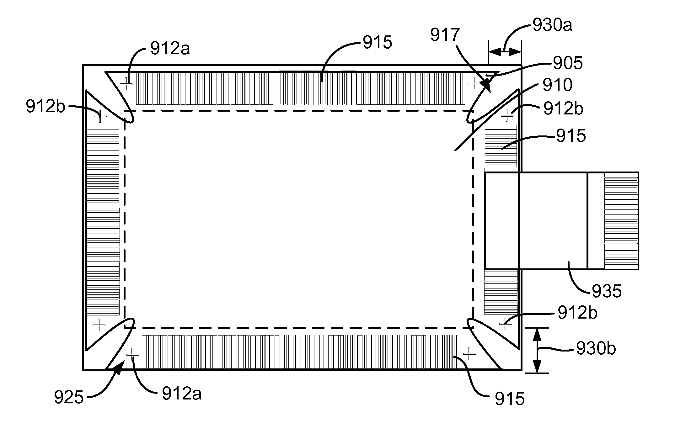
cts a bottom view of a “flex behind backplate” configuration according to some embodiments described herein.

[0030]FIG. 9B depicts a cross-sectional view of a configuration similar to that shown in FIG. 9A.

[0031]FIG. 10 depicts a bottom view of an alternative configuration.

[0032]FIG. 11 is flow chart that sets forth steps of fabricating devices according to some methods described herein.

[0033]FIG. 12 is flow chart that sets forth steps of fabricating devices according to some alternative methods described herein.

[0034]FIG. 13A depicts a bottom view of a dual “flex behind backplate” configuration according to some embodiments described herein.

[0035]FIG. 13B depicts a cross-sectional view of the configuration shown in FIG. 13A.

DETAILED DESCRIPTION

[0036]While the present invention will be described with reference to a few specific embodiments, the description and specific embodiments are merely illustrative of the invention and are not to be construed as limiting the invention. Various ...


PUM


Abstract

Various embodiments described herein involve making connections with the display leads on more than one side of the display array, e.g., on 2 sides, 3 sides or all 4 sides of the display array. By making connections with the display leads on more than one side of the display array, the available area for bonding leads and control circuitry may be increased. The driver chip(s), discrete components, and other active components necessary for addressing the display panel may be attached to the top or the bottom of a flexible printed circuit (“FPC”) or a similar device. Some embodiments involve attaching an FPC to the display such that that the backplate is substantially encased by the FPC.

Description

FIELD OF THE INVENTION[0001]This application relates generally to display technology and more specifically to circuitry for controlling displays.DESCRIPTION OF RELATED TECHNOLOGY[0002]In general, consumers of portable devices having video capability would like to have the display occupy as much of the front surface of the portable device as possible. Accordingly, there is continued pressure for designers and manufacturers to reduce the display panel periphery (also referred to herein as “ledges”), used for display routing outside the active area of the display, in order to proportionately increase the active area of the display relative to the total front surface area. Consumers also want the portable displays to have increasingly higher resolution. Higher resolution displays require increased numbers of leads to conduct signals to the active area of the display. Increasing the number of leads means that more leads need to be connected to a driver chip, routed around the corners of ...

Claims


Application Information

Patent Timeline
Patent Type & Authority Applications(United States)
IPC IPC(8): G09G3/34H01J9/00H01J9/20
CPCG02B26/001H05K2201/10128H05K1/189G02F1/13452
Inventor LIN, PENG CHENGMATHEW, MITHRAN CHERIYAN
Owner SNAPTRACK
Why Eureka
Try Eureka