LED lamp
a technology of led lamps and led lamps, applied in the field of lighting, can solve the problems of heat dissipation of high-power led lamps, attenuation of lighting efficiency, direct impact on the life of led lamps, etc., and achieve the effects of increasing the available area of heat dissipation, increasing the usable space, and increasing the heat dissipation area
- Summary
- Abstract
- Description
- Claims
- Application Information
AI Technical Summary
Benefits of technology
Problems solved by technology
Method used
Image
Examples
first embodiment
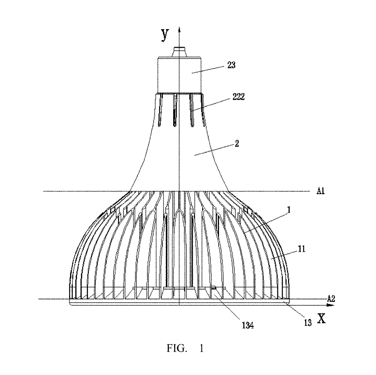
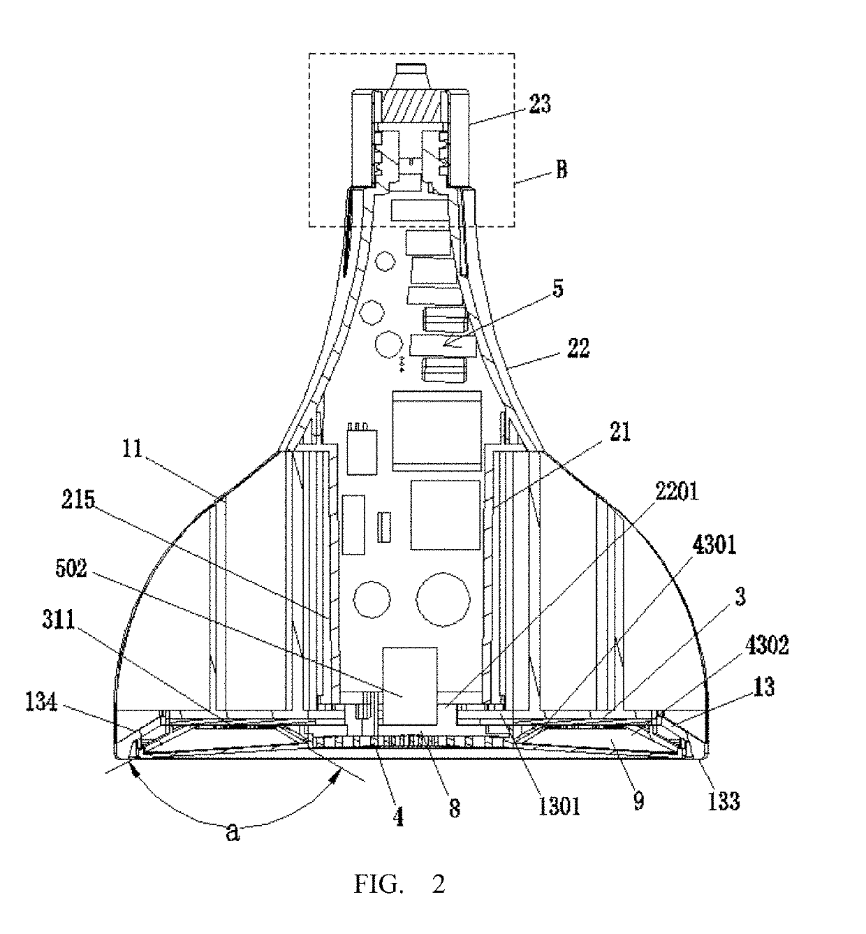
[0196]As shown in FIG. 36a, which shows the heat sink 10. The heat sink 10 includes first fins 101 and second fins 102. The heat sink 10 is defined with a first circumference R1 and a second circumference R2, which are projected onto the base 130. The first circumference R1 is less than the second circumference R2. On the base 130, the first fins 101 extend into a cylindrical room (the part for receiving the sleeve 21, the cylindrical room mentioned in the following embodiments is the same as this) but do not exceed the second circumference R2. For example, the first fins 101 extend from the cylindrical room right to the first circumference R1. The second fins 102 extend to the first circumference R1 but do not exceed the second circumference R2, e.g. just extend to the second circumference R2. In a radial direction, both the first fins 101 and the second fins 102 are interlacedly arranged. Each adjacent of the second fins 102 is symmetrically arranged about one of the first fins 10...
third embodiment
[0199]The fins of the third embodiment may be further expanded to the nth fin, where n is an integer greater than two. For example, the first circumference R1 through the nth circumference with gradually getting bigger are defined on the base 130. The first fins 101 extend from the cylindrical room to the first circumference R1. The nth fin extends from the (n−1)th circumference to the nth circumference. In a radial direction, the (n−1)th fin and the nth fin are interlacedly arranged. Each two nth fins are symmetrically arranged about one of the (n−1)th fins. In addition, from first fin 101 to the nth fin, at least part thereof overlap with the light board 3 (a projection in an axial direction of the LED board 3) to ensure a direct thermal conduction path existing between the LED light board 3 and the fins.
[0200]As shown in FIG. 36c, the nth fin and the (n−1)th fin are interlaced but do not overlap. An outer edge of the (n−1)th fin does not exceed the (n−1)th circumference. The nth ...
second embodiment
[0455]In other embodiments, the bias generating circuit may also be used for providing a working voltage to a temperature sensing circuit 700. FIG. 80 is a circuit diagram of the bias generating circuit of the invention. FIG. 81 is a circuit diagram of a temperature sensing circuit of an embodiment of the invention. As shown in FIGS. 80 and 81, the temperature sensing circuit 700 electrically connects to power converter 400 for sending temperature detecting signal to power converter 400. The temperature sensing circuit 700 has a temperature sensor electrically connecting to bias generating circuit 600b to make bias generating circuit 600b provide a working voltage to temperature sensing circuit 600b.
[0456]In this embodiment, in comparison with the embodiment shown in FIG. 79, the bias generating circuit 600b of this embodiment further includes a transistor Q3, a diode D6, a resistor R12 and a capacitor C10. Transistor Q3 may be a BJT as an example (hereinafter refer as BJT Q3). The...
PUM
 Abstract
Description
Claims
Application Information
 - R&D
- Intellectual Property
- Life Sciences
- Materials
- Tech Scout
- Unparalleled Data Quality
- Higher Quality Content
- 60% Fewer Hallucinations
Browse by: Latest US Patents, China's latest patents, Technical Efficacy Thesaurus, Application Domain, Technology Topic, Popular Technical Reports.
© 2025 PatSnap. All rights reserved.Legal|Privacy policy|Modern Slavery Act Transparency Statement|Sitemap|About US| Contact US: help@patsnap.com


