
Dual-Deflecting Electrophysiology Catheter

Active Publication Date: 2011-10-20
ST JUDE MEDICAL ATRIAL FIBRILLATION DIV
View PDF5 Cites 14 Cited by
  • Summary
  • Abstract
  • Description
  • Claims
  • Application Information

AI Technical Summary

Benefits of technology

Accordingly, it is an object of the present invention to provide an electrophysiology catheter having an enhanced ability to customize the shape of the catheter for a particular patient's individual anatomy.
Another object of the present invention is to provide an electrophysiology catheter that allows the looped portion to deflect relative to the remainder of the catheter body, thereby permitting the angle of the loop to be “fine tuned.”
An advantage of an electrophysiology catheter according to the present invention is that the distal region thereof, including the loop used in electrophysiological procedures at or near an annular region, can be deflected relative to the remainder of the catheter body.
Another advantage of an electrophysiology catheter according to the present invention is that its shape can be tailored to a particular patient's individual anatomy.

Problems solved by technology

Because of varying patient anatomies, however, it may be challenging to properly place the looped section of the catheter precisely in the pulmonary vein ostia.

Method used


Image

  • Dual-Deflecting Electrophysiology Catheter
  • Dual-Deflecting Electrophysiology Catheter
  • Dual-Deflecting Electrophysiology Catheter

Examples


Embodiment Construction

The present invention will be described with reference to an electrophysiology catheter utilized in cardiac electrophysiology studies, such as the Livewire Spiral HP™ and Inquiry™ Optima™ PLUS catheters of St. Jude Medical, Inc. It should be understood, however, that the present teachings may be applied to good advantage in other contexts as well.

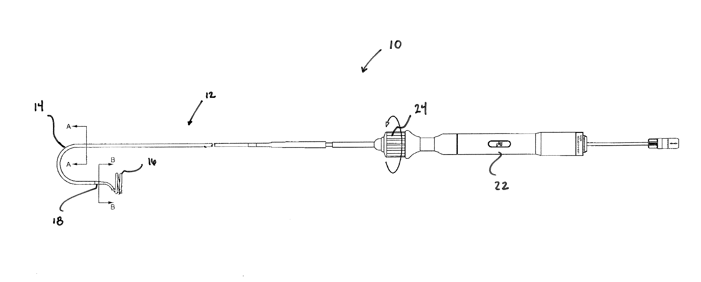
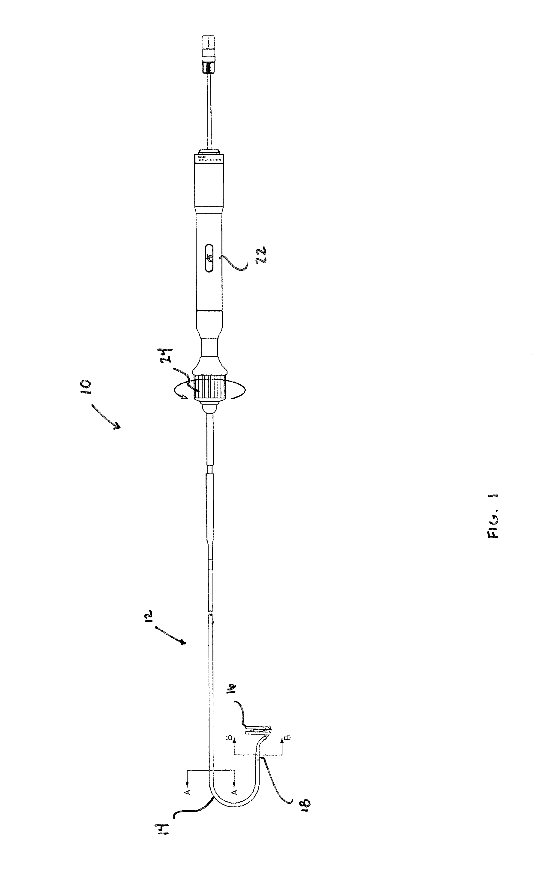
Referring now to the figures, FIG. 1 depicts an electrophysiology (“EP”) catheter 10 according to a first aspect of the present invention.

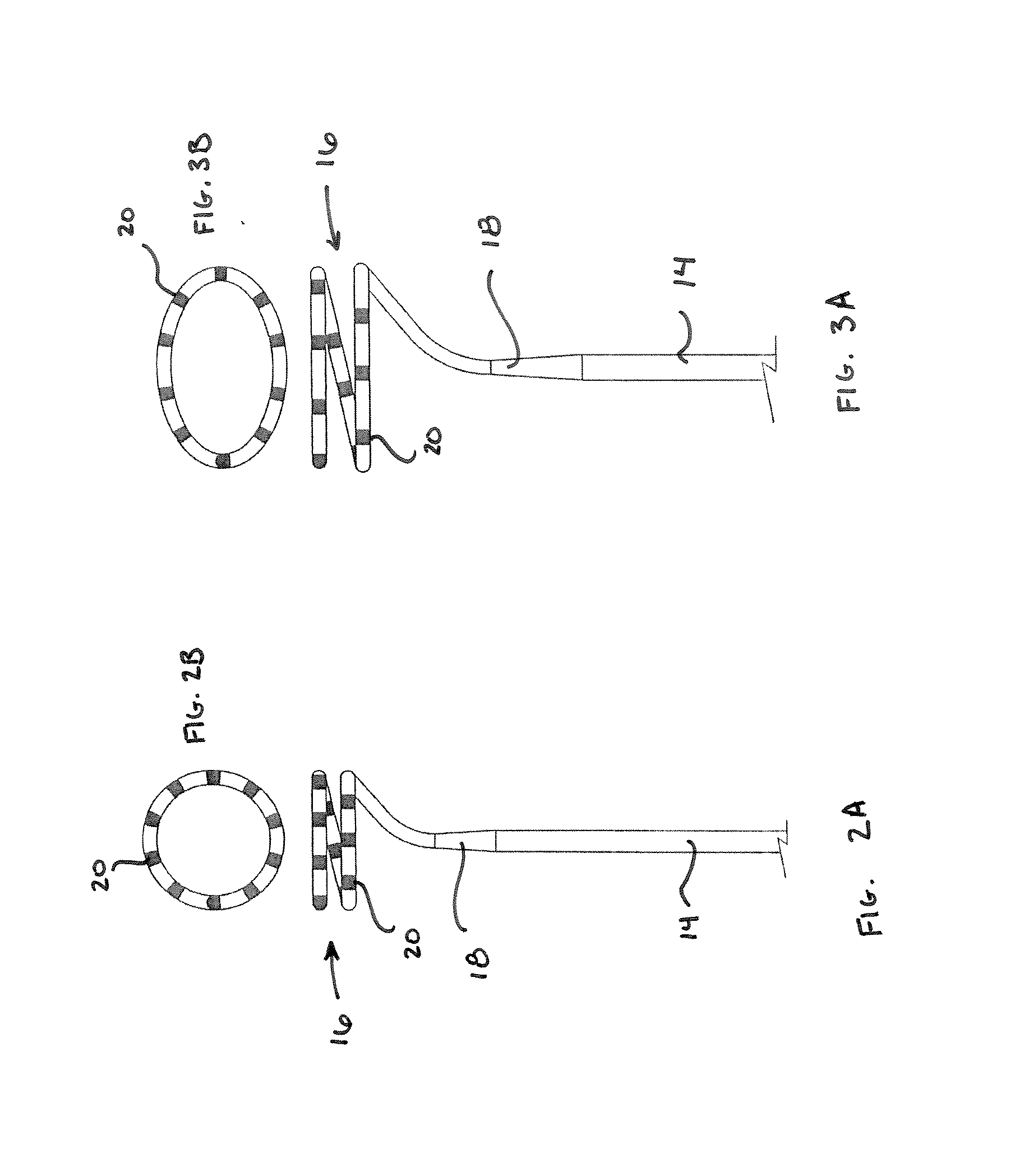
EP catheter 10 generally includes an elongate catheter body 12, which, in some embodiments, is tubular (e.g., it defines at least one lumen therethrough). Catheter body 12 includes a proximal region 14, a distal region 16, and a neck region 18 between proximal region 14 and distal region 16. One of ordinary skill in the art will appreciate that the relative lengths of proximal region 14, distal region 16, and neck region 18 depicted in FIG. 1 are merely illustrative and may vary without departing from the...


PUM


Abstract

An electrophysiology catheter includes a tubular body having a proximal region, a neck region, and a distal region predisposed into a loop and including electrodes. A first deflection wire extends through at least a portion of the proximal region of the catheter body and includes a first flattened section, while a second deflection wire extends through the neck region and at least a portion of the distal region and includes a second flattened section within the neck region. A first activation wire is joined to the flattened section of the first deflection wire, while a second activation wire is joined to the flattened section of the second deflection wire. Thus, forces acting on the first and second activation wires, such as forces imposed by a handle-based actuator, are respectively transmitted to the first and second deflection wires, thereby deflecting the proximal and neck regions, respectively.

Description

BACKGROUND OF THE INVENTIONa. Field of the InventionThe instant invention relates to catheters for use in medical procedures. In particular, the instant invention relates to an electrophysiology catheter for use in diagnostic and therapeutic procedures at or near an annular region of a patient's anatomy, such as the ostium of a pulmonary vein.b. Background ArtCatheters are used for an ever-growing number of procedures. For example, catheters are used for diagnostic, therapeutic, and ablative procedures, to name just a few examples. Typically, the catheter is manipulated through the patient's vasculature and to the intended site, for example a site within the patient's heart.A typical electrophysiology catheter includes an elongate shaft and one or more electrodes on the distal end of the shaft. The electrodes may be used for ablation, diagnosis, or the like. Oftentimes, these electrodes are ring electrodes that extend about the entire circumference of the catheter shaft.One specific...

Claims


Application Information

Patent Timeline
IPC IPC(8): A61B5/04A61B5/296
CPCA61B5/0422A61M25/0147A61B5/6856A61B5/6855A61B5/287
Inventor DE LA RAMA, ALANPHUNG, PHUONG-OANHROY, PIANKA
Owner ST JUDE MEDICAL ATRIAL FIBRILLATION DIV
Learn More