Anti-drone detection system and its control method
A detection system, anti-UAV technology, applied in radio wave measurement systems, measurement devices, computer parts and other directions, can solve problems such as reducing the efficiency and effectiveness of UAV reconnaissance, and achieve trigger and I/O pins The effect of richness, low power consumption, and reduced storage and computation
- Summary
- Abstract
- Description
- Claims
- Application Information
AI Technical Summary
Problems solved by technology
Method used
Image
Examples
Embodiment 1
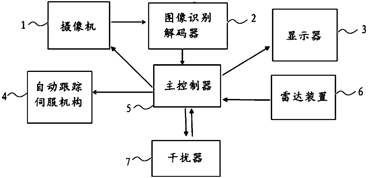
[0047] Such as figure 1 As shown, the anti-drone detection system includes a camera 1 with an optical lens, a display 3, an automatic tracking servo mechanism 4 for controlling the movement of the camera, a radar device 6, a main controller 5, a jammer 7 and a picture of a drone stored therein. Image recognition decoder 2 for information; the signal output end of the camera 1 is connected to the signal input end of the image recognition decoder 2, and the signal output end of the image recognition decoder 2 is connected to the first of the main controller 5 signal input end, the signal output end of the radar device 6 is connected to the second signal input end of the main controller 5, and the first signal output end of the main controller 5 is connected to the signal input end of the camera 1, so The second signal output end of the main controller 5 is connected to the signal input end of the display 3, the third signal output end of the main controller 5 is connected to the...
Embodiment 2
[0049] This embodiment is on the basis of embodiment 1:
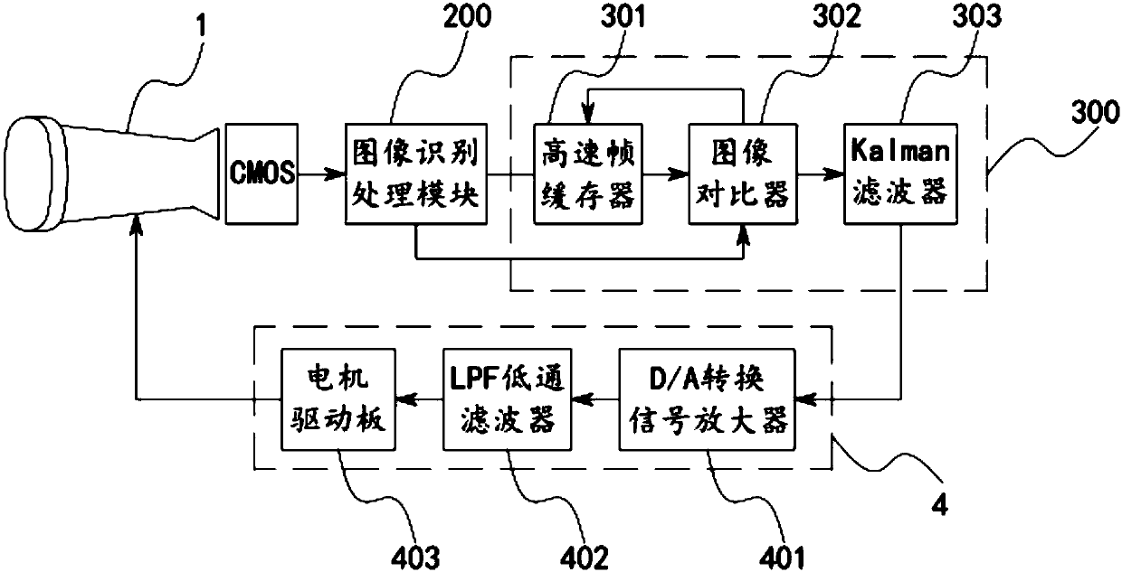
[0050] Such as image 3 As shown, the image recognition decoder 2 includes an image recognition processing module 200 and an image analysis module 300, the signal output end of the image recognition processing module 200 is connected to the signal input end of the image analysis module 300; the image analysis module 300 includes a high-speed frame buffer 301, an image comparator 302 and a Kalman filter 303, the first signal input end of the image comparator 302 is connected to the signal output end of the image recognition processing module 200, and the high-speed frame buffer 301 The signal output end of the image comparator 302 is connected to the second signal input end of the image comparator 302, the signal input end of the high-speed frame buffer 301 is connected to the first signal output end of the image comparator 302, and the image comparator 302 The second signal output end is connected to the signal input e...
Embodiment 3
[0052] This embodiment is on the basis of embodiment 2:
[0053] The Kalman filter 303 has a built-in FPGA chip for implementing the Kalman algorithm.
[0054] Such as image 3 and Figure 4 As shown, the automatic tracking servo mechanism 4 of the present invention includes a horizontal drive motor that drives the camera to move in the horizontal direction, a vertical drive motor that drives the camera to move in the vertical direction, a motor drive board 403, an LPF low-pass filter 402 and a D / A conversion signal amplifier 401, the signal input end of the D / A conversion signal amplifier 401 is connected to the signal output end of the Kalman filter 303, and the signal output end of the D / A conversion signal amplifier 401 is connected to the LPF low pass The signal input end of the filter 402, the signal output end of the LPF low-pass filter 402 is connected to the signal input end of the motor drive board 403, and the first signal output end of the motor drive board 403 ...
PUM
 Abstract
Description
Claims
Application Information
 - R&D
- Intellectual Property
- Life Sciences
- Materials
- Tech Scout
- Unparalleled Data Quality
- Higher Quality Content
- 60% Fewer Hallucinations
Browse by: Latest US Patents, China's latest patents, Technical Efficacy Thesaurus, Application Domain, Technology Topic, Popular Technical Reports.
© 2025 PatSnap. All rights reserved.Legal|Privacy policy|Modern Slavery Act Transparency Statement|Sitemap|About US| Contact US: help@patsnap.com


