Elevator installation

a technology for installing elevators and escalators, which is applied in the direction of elevators, instruments, computer control, etc., can solve the problems of large variations in braking travel, long stopping paths, and braking distances, and achieve reliable activation of respective braking devices, high operational safety, and low cost

Active Publication Date: 2011-10-27
INVENTIO AG
View PDF10 Cites 12 Cited by
  • Summary
  • Abstract
  • Description
  • Claims
  • Application Information

AI Technical Summary

Benefits of technology

[0016]It is advantageous if the safety system comprises a relative sensor which is provided at the first elevator car and serves for detection of a spacing between the first elevator car and the second elevator car. Alternatively or in addition thereto the safety system comprises a relative sensor which is provided at the second elevator car and serves for detection of a spacing between the first elevator car and the second elevator car. Finally, for preventing a collision between the first elevator car and the second elevator car the safety system drive activates the braking device of the first elevator car and/or the braking device of the second elevator car in dependence on the detected spacing between the first elevator car and the second elevator car. In this connection it is additionally advantageous that the safety system comprises a decentral safety device, which is provided at the first elevator car and which activates the braking device of the first elevator car in dependence on the spacing detected by the relative sensor provided at the first elevator car, and a decentral safety device, wh

Problems solved by technology

The elevator installation known from EP 1 562 848 B1 has the disadvantage that large variations with respect to the braking travel arise, since the preset normal force generates, due to varying coefficients of friction, varying braking forces and these in turn produce

Method used


Image

  • Elevator installation
  • Elevator installation
  • Elevator installation

Examples


Embodiment Construction

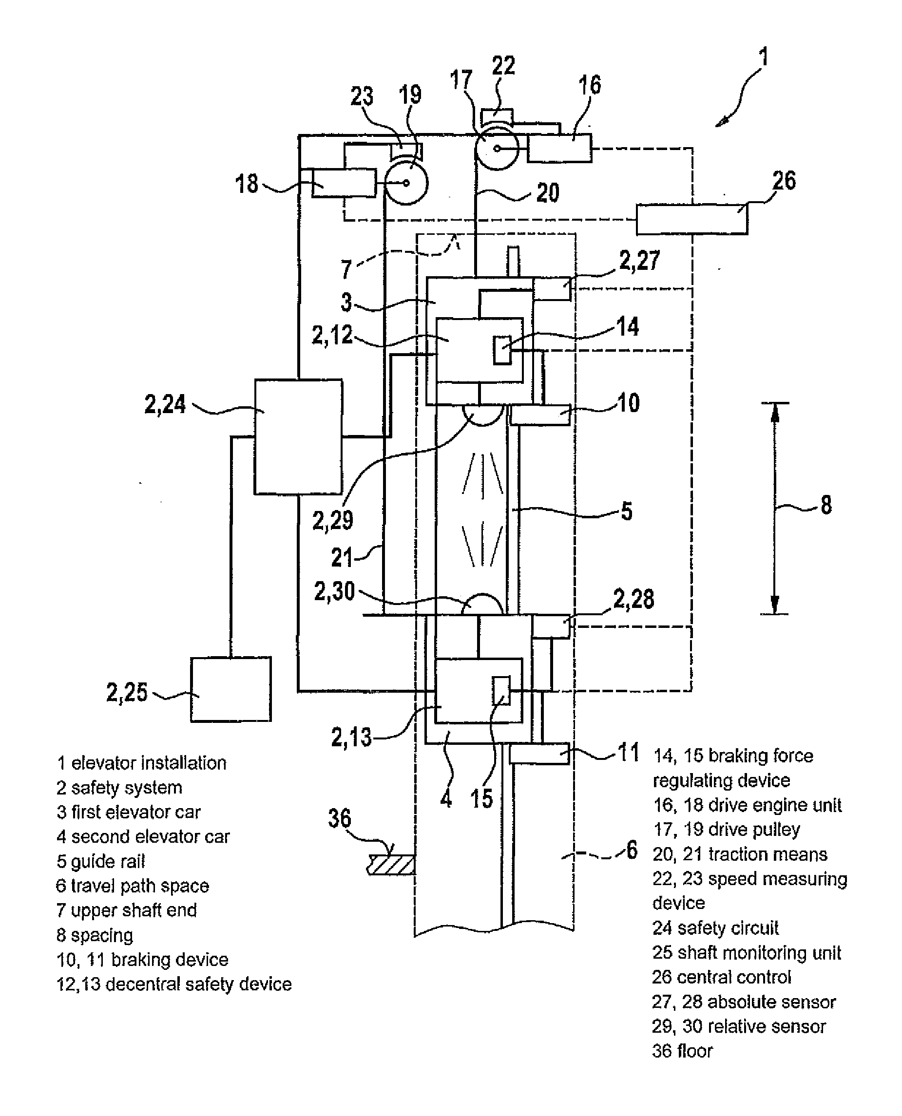
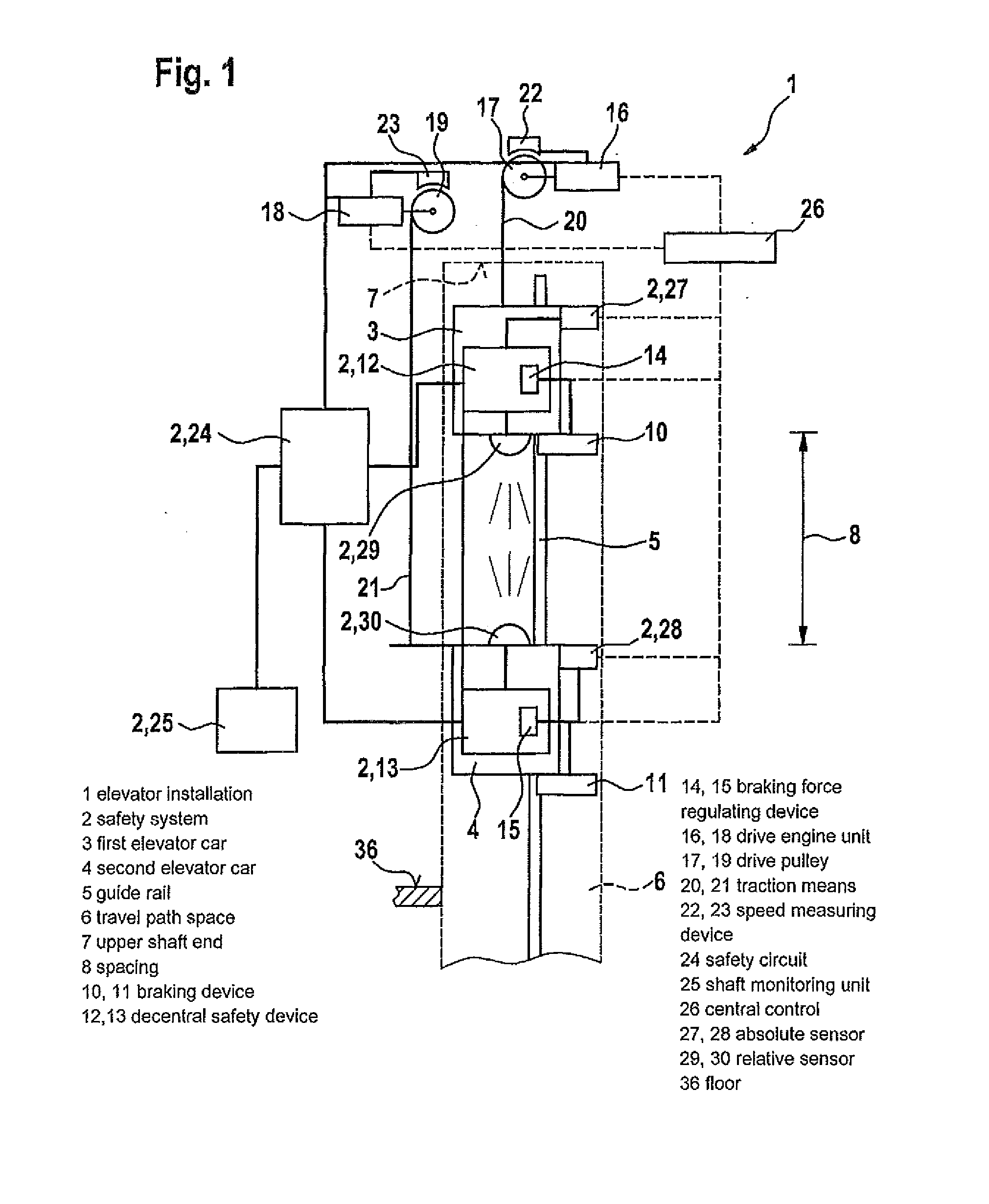
[0023]FIG. 1 shows an elevator installation with a safety system 2 in a schematic illustration in correspondence with a first exemplifying embodiment. The elevator installation 1 of this exemplifying embodiment comprises a first elevator car 3 and a second elevator car 4. Depending on the respective design of the elevator installation 1, however, also more than two elevator cars 3, 4 can be provided. The elevator cars 3, 4 are guided at a common guide rail 5 which predetermines a travel path 5 for the elevator cars 3, 4.

[0024]The elevator cars 3, 4 during their journey along the guide rails 5 cross a travel path space 6 which is illustrated as a section in FIG. 1. The travel space 6 in this exemplifying embodiment is crossed by two elevator cars 3, 4. However, a position at the upper shaft end 7 is reachable only by the elevator car 3, whilst a corresponding position at a lower shaft end (not illustrated) is reachable only by the second elevator car 4.

[0025]In operation the first el...


PUM


Abstract

An elevator installation includes a first elevator car and a second elevator car, each having a respective braking device, and a safety system that monitors the elevator cars. The safety system has for each braking device a braking force regulating device for regulating a braking force of the respective braking device. The safety system activates at least one of the braking devices by the associated braking force regulating device in order to prevent collision of the first elevator car with the second elevator car.

Description

FIELD OF THE INVENTION[0001]The invention relates to an elevator installation with a first elevator car and at least one second car, which are arranged, for example, in a common elevator shaft and in operation cross this elevator shaft along a common travel path.BACKGROUND OF THE INVENTION[0002]An elevator installation with a shaft in which at least two cars are movable along a common travel path is known from DE 1 562 848 B1. In the known elevator installation the cars each comprise a safety brake device with which a control unit, a drive and a brake are associated. In addition, a shaft information system, which is connected with an electrical safety device, for determination of the positions and speeds of the cars is provided. In that case spacing sensors are provided which serve for determination of the spacing adopted by a specific car from an adjacent car or a travel path end and preferably also from a predetermined shaft point are provided, wherein the spacing sensors are conn...

Claims


Application Information

Patent Timeline
IPC IPC(8): B66B5/00B66B1/32
CPCB66B5/0031
Inventor SILBERHORN, GERTKOCHER, HANSGRUNDMANN, STEFFEN
Owner INVENTIO AG
Why Eureka
Try Eureka