Buffer Circuit for a Capacitive Load of High Value

a buffer circuit and capacitive load technology, applied in logic circuits, transmission line coupling arrangements, electric pulse generators, etc., can solve problems such as problems appearing

Active Publication Date: 2011-10-27
STMICROELECTRONICS SRL
View PDF2 Cites 15 Cited by
  • Summary
  • Abstract
  • Description
  • Claims
  • Application Information

AI Technical Summary

Problems solved by technology

In the case of buffers intended to power a capacitive load, problems may appear if the c...

Method used


Image

  • Buffer Circuit for a Capacitive Load of High Value
  • Buffer Circuit for a Capacitive Load of High Value
  • Buffer Circuit for a Capacitive Load of High Value

Examples


Embodiment Construction

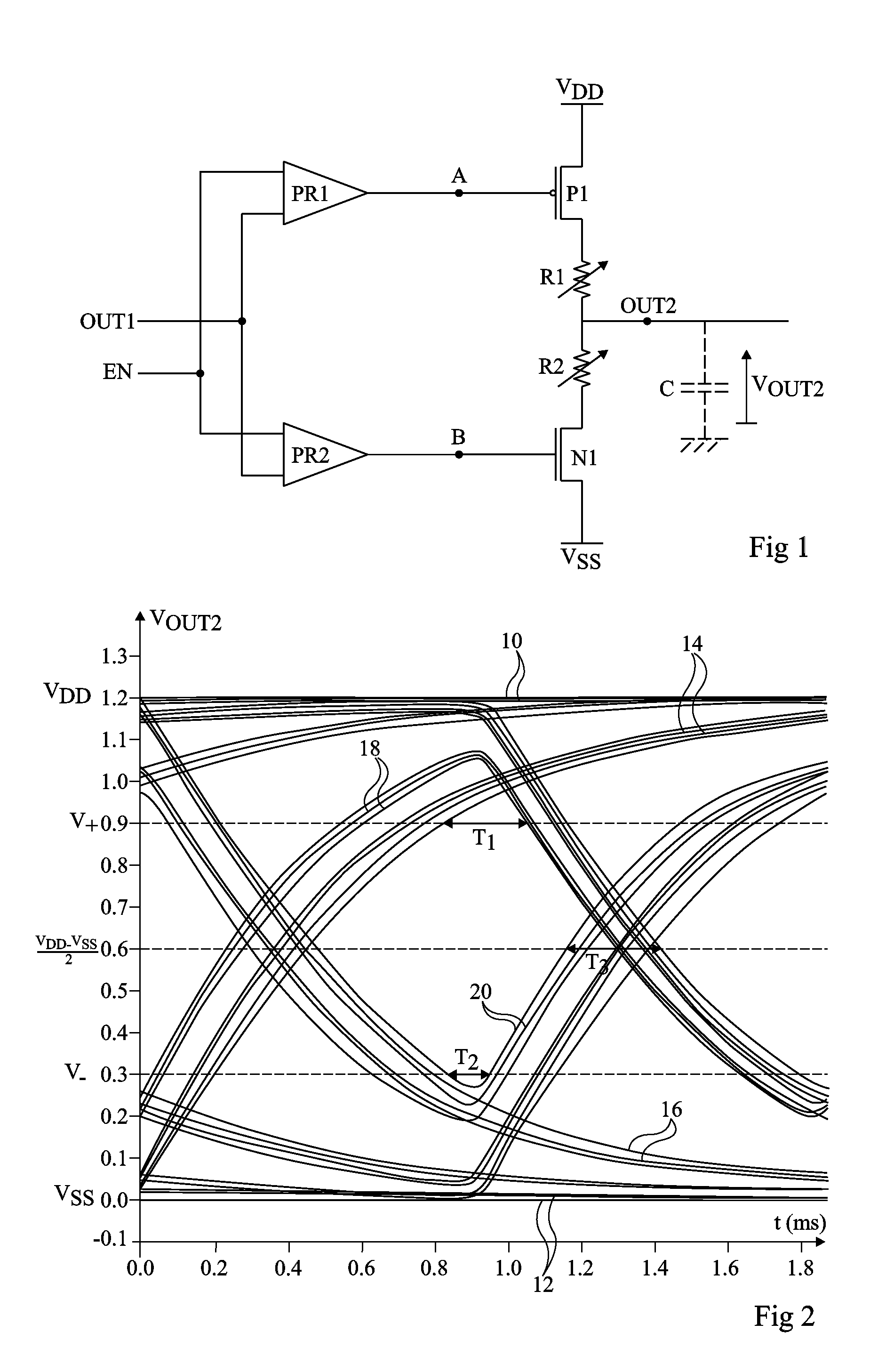
[0029]Before addressing the illustrated embodiments in detail, objects and advantages of embodiments of the invention will be discussed generally. An object of an embodiment of the present invention is to provide a buffer enabling an improved data transmission. Another object of an embodiment of the present invention is to provide a buffer having a large eye opening and a low jitter.

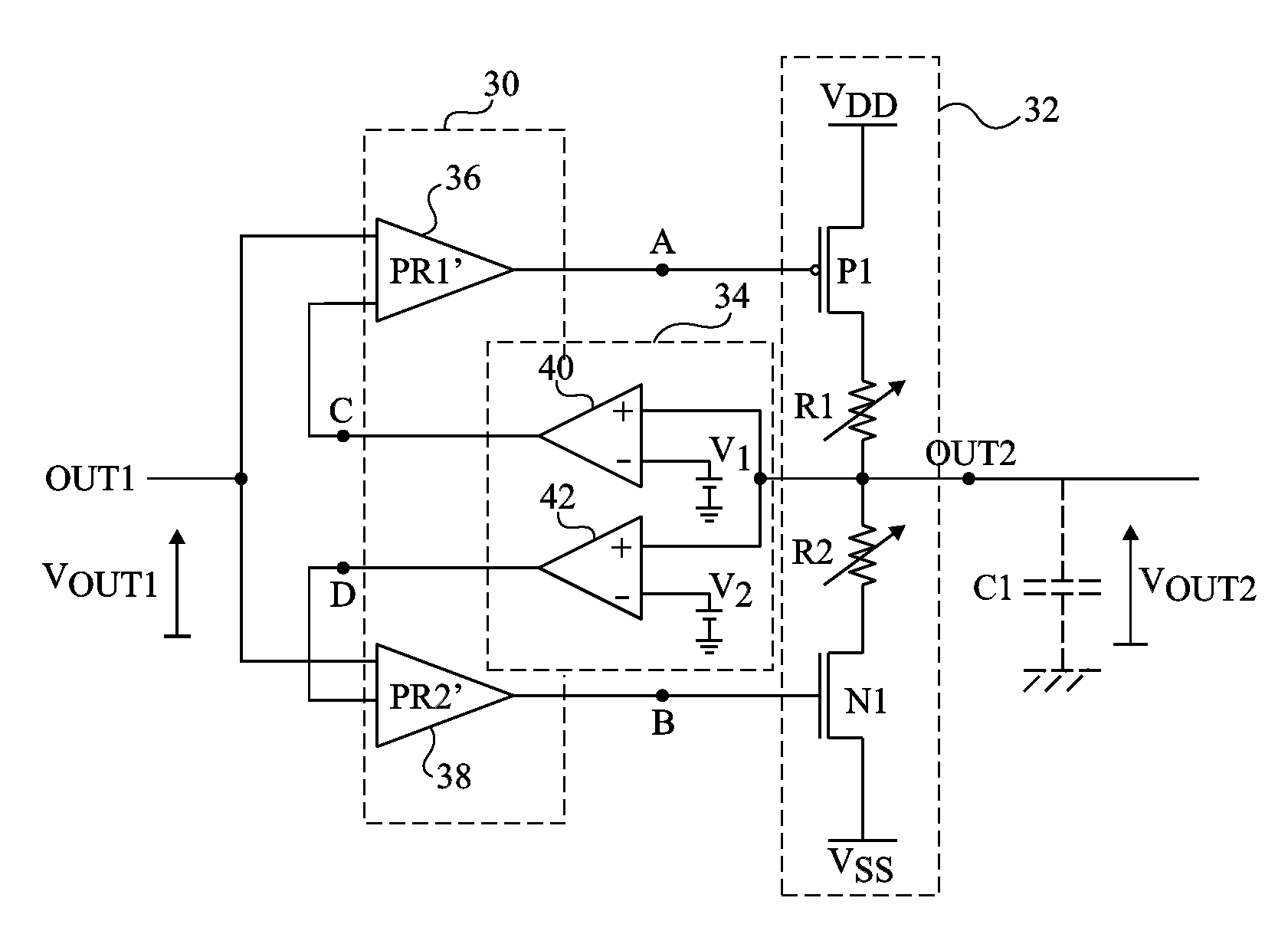
[0030]To obtain a buffer with a large opening and a low jitter, the transistors constitutive of a buffer connecting an output capacitive load to a high or low power supply are disconnected when the output voltage exceeds a predetermined threshold.

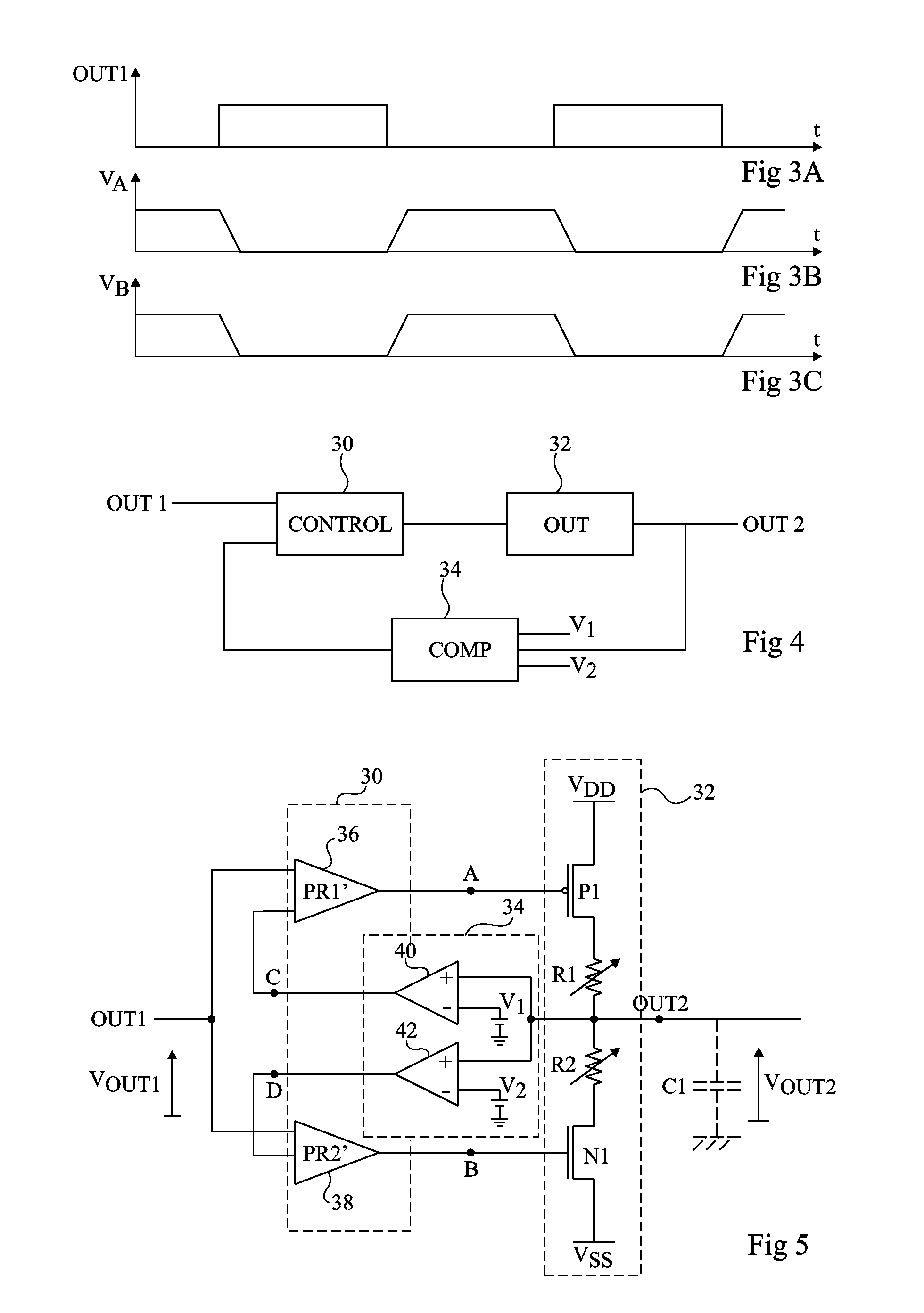
[0031]Thus, an embodiment of the present invention provides a buffer circuit comprising an input terminal capable of receiving an input signal and an output terminal capable of being connected to a capacitive load, comprising: an output circuit comprising at least a series connection, between two terminals of application of a power supply voltage, of a first MOS...


PUM


Abstract

A buffer circuit including an input terminal capable of receiving an input signal and an output terminal capable of being connected to a capacitive load, including an output circuit a series connection, between two terminals of application of a power supply voltage, of a first MOS transistor, a first and a second resistor of adjustable values, and a second MOS transistor, and means for controlling said first and second transistors receiving the input signal The buffer circuit further includes means for comparing the voltage on the output terminal of the circuit with at least one threshold voltage, the comparison means being connected to said control means.

Description

CROSS REFERENCE TO RELATED APPLICATIONS[0001]This application claims the benefit of French Patent Application No. 10 / 53028, filed Apr. 21, 2010 and entitled “Buffer Circuit For a Capacitive Load of High Value,” which is hereby incorporated by reference to the maximum extent allowable by law.TECHNICAL FIELD[0002]The present invention relates to buffer circuits intended to match the output of a data transmission circuit with a capacitive load of high value.BACKGROUND[0003]Buffer circuits are circuits having an output similar to their input, but where shape and / or amplitude deformations likely to affect the input have been corrected. Buffer circuits thus enable adjusting the level of a signal which might otherwise be wrongly interpreted if no buffer was used. The buffers considered herein enable one to transform a high input impedance into a low output impedance.[0004]In the case of buffers intended to power a capacitive load, problems may appear if the capacitive load has a high value...

Claims


Application Information

Patent Timeline
IPC IPC(8): H03K5/153
CPCH03K19/0013H03K19/00323H04L25/0266H03K19/018521H03K19/018585H03K19/00384
Inventor AGUT, FRANCOIS
Owner STMICROELECTRONICS SRL
Why Eureka
Try Eureka