
Method of driving stereoscopic display apparatus and stereoscopic display apparatus

a technology of stereoscopic display and display apparatus, which is applied in the direction of instruments, computing, electric digital data processing, etc., can solve the problems of increasing power consumption due to light emission during, light emission, and inability to collectively display or not to display, and achieves the effect of less power consumption

Active Publication Date: 2011-10-27
JOLED INC
View PDF7 Cites 16 Cited by
  • Summary
  • Abstract
  • Description
  • Claims
  • Application Information

AI Technical Summary

Benefits of technology

[0010]Specifically, with the above stereoscopic display apparatus, a video signal of one frame is divided into a video signal for the right eye and a video signal for the left eye so as to be separately displayed on the display unit, thereby resulting in, as compared to the case of not performing stereoscopic display, an increase in the drive frequency for the scanning performed for the display of the video signals on the display unit. It also results in an increase in the power consumption due to light emission during a time in which light emission is unnecessary, such as when the video signal for the right eye is displayed while the right-eye shutter is closed.
[0012]In view of the above problems, the present invention aims to provide a method of driving a stereoscopic display apparatus and a stereoscopic display apparatus for displaying stereoscopic video with less power consumption without raising the drive frequency.
[0014]With the method of driving a stereoscopic display apparatus and the stereoscopic display apparatus according to the present invention, stereoscopic video can be displayed with less power consumption without raising the drive frequency.

Problems solved by technology

However, the above conventional technique has caused the following problems.
It also results in an increase in the power consumption due to light emission during a time in which light emission is unnecessary, such as when the video signal for the right eye is displayed while the right-eye shutter is closed.
Consequently, the display of the video signals on the display unit is performed on a per-scanning line basis, and it is not possible to collectively display or collectively not display the video signals of one frame on the entire screen.
This has resulted in an increase in the power consumption due to light emission during a time in which light emission is unnecessary.

Method used


Image

  • Method of driving stereoscopic display apparatus and stereoscopic display apparatus
  • Method of driving stereoscopic display apparatus and stereoscopic display apparatus
  • Method of driving stereoscopic display apparatus and stereoscopic display apparatus

Examples


first embodiment

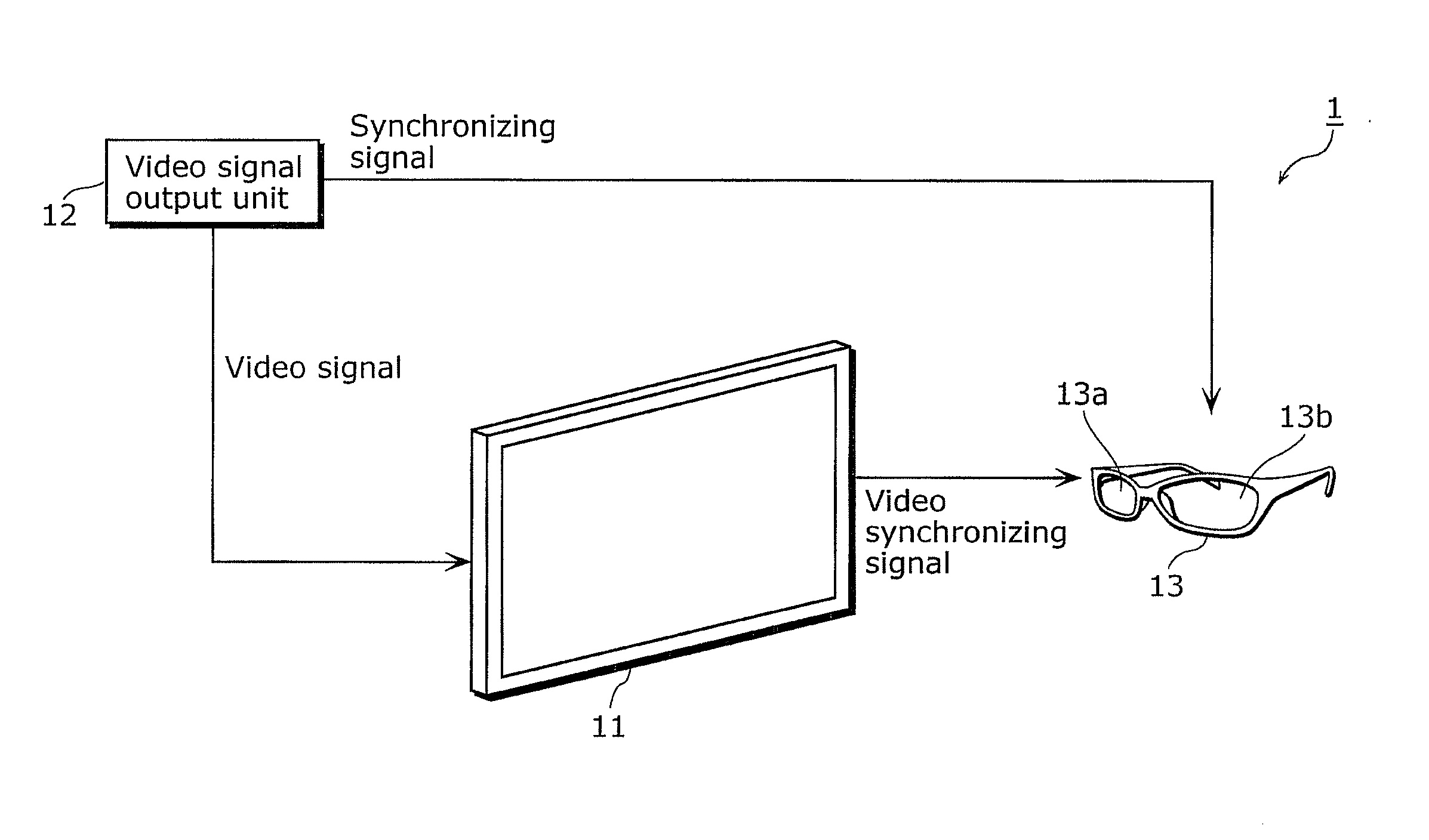
[0055]A method of driving a stereoscopic display apparatus according to a first embodiment of the present invention is a method of driving a stereoscopic display apparatus, the stereoscopic display apparatus including: an image display unit including a display unit configured to sequentially display a right-eye image and a left-eye image; and a pair of glasses with which the right-eye image and the left-eye image can be sequentially viewed, the method including the following steps performed for the display unit: a first step of writing, when a first display region including a plurality of rows is in an image displaying state, image data to a second display region including a plurality of rows different from the plurality of rows included in the first display region; a second step of putting the second display region in the image displaying state and putting the first display region in an image not-displaying state after the image data is written to the second display region; a third...

second embodiment

[0118]Next, the video display system according to a second embodiment of the present invention is described.

[0119]The second embodiment is different from the first embodiment in that a first control unit 23a and a second control unit 23b are included in the control circuit 23 instead of the third scanning line drive circuit and the fourth scanning line drive circuit included in the scanning signal transfer unit 25, so as to put the video display unit in the image displaying state or the image not-displaying state on the odd-numbered-block basis or on the even-numbered-block basis.

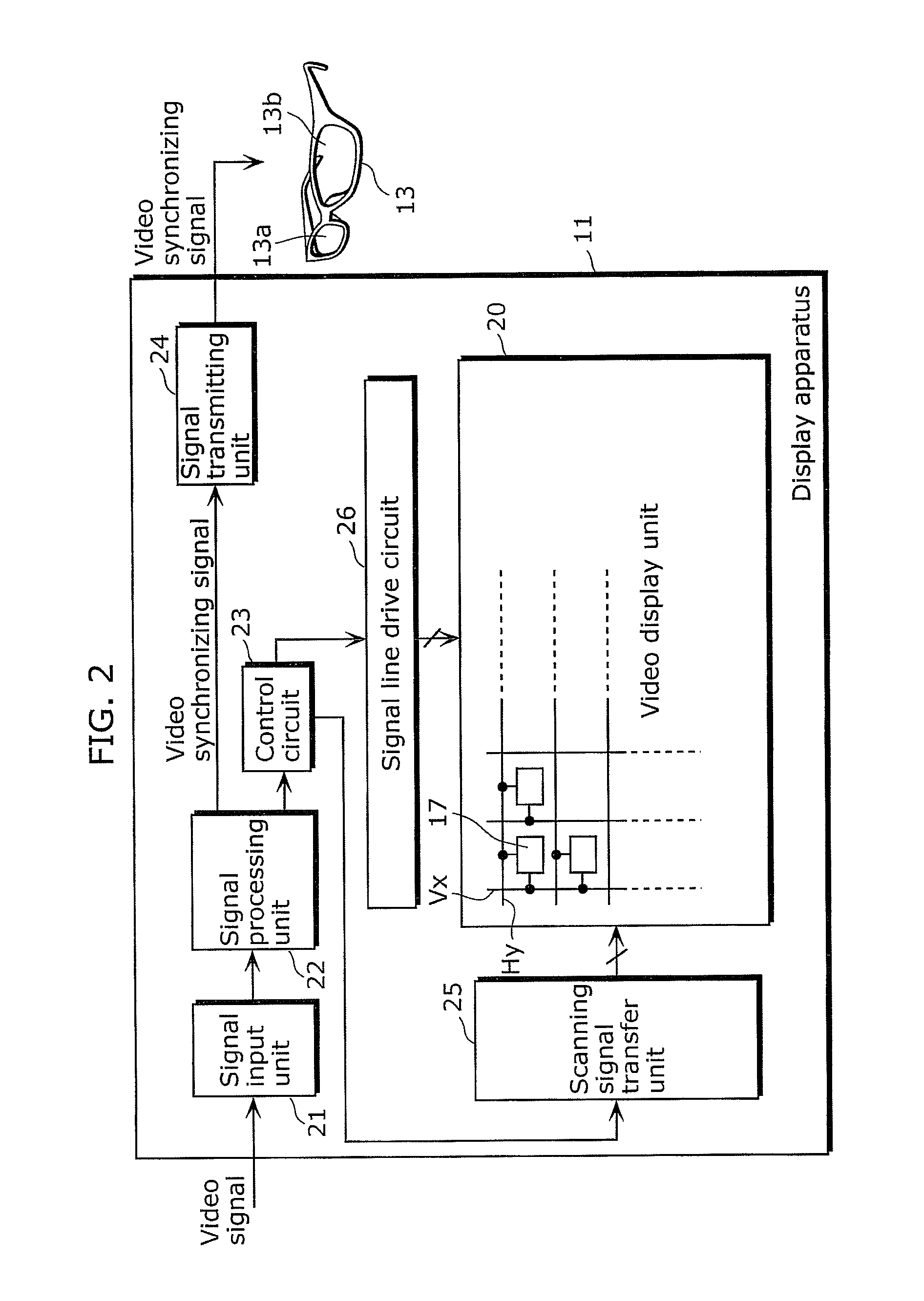
[0120]FIG. 13 shows a detailed configuration of the video display unit 20, the scanning signal transfer unit 25, the signal line drive circuit 26, and the control circuit 23 included in the display apparatus 11. As shown in FIG. 13, the control circuit 23 includes the first control unit 23a and the second control unit 23b. The first control unit 23a and the second control unit 23b correspond, respectively, ...

third embodiment

[0128]Next, the video display system according to a third embodiment of the present invention is described.

[0129]The third embodiment is different from the first embodiment in that each pixel unit provided in the video display unit includes a liquid crystal element instead of an organic EL element.

[0130]FIG. 16 is a block diagram showing a configuration of a display apparatus included in the video display system according to the third embodiment. As shown in FIG. 16, a display apparatus 111 includes: a video display unit 120, a signal input unit 121, a signal processing unit 122, a control circuit 123, a signal transmitting unit 124, a scanning line drive circuit 125, and a signal line drive circuit 126. Note that the video display unit 120, the control circuit 123, the scanning line drive circuit 125, and the signal line drive circuit 126 correspond, respectively, to the display unit, the display control unit, the scanning line drive unit, and the data line drive unit in the presen...


PUM


Abstract

A stereoscopic display includes an image displayer. The image displayer includes a display that is configured to sequentially display a right-eye image and a left-eye image. The display includes a first region that includes first rows and a second region that includes second rows. A method of driving the stereoscopic display includes sequentially repeating: writing first image data to the second region when the first region is in an image displaying state; setting the second region to the image displaying state and the first region to an image not-displaying state after the image data is written to the second region; writing second image data to the first region when the second region is in the image displaying state; and setting the first region to the image displaying state and the second region to the image not-displaying state after the second image data is written to the first region.

Description

CROSS REFERENCE TO RELATED APPLICATION[0001]This is a continuation application of PCT Application No. PCT / JP10 / 002,342, filed on Mar. 31, 2010, designating the United States of America, the disclosure of which, including the specification, drawings and claims, is incorporated herein by reference in its entirety.BACKGROUND OF THE INVENTION[0002]1. Field of the Invention[0003]The present invention relates to a method of driving a stereoscopic display apparatus adapted to display stereoscopic video, and to a stereoscopic display apparatus.[0004]2. Description of the Related Art[0005]Conventionally, various methods have been considered to display stereoscopic video. As an example, there is a method for generating stereoscopic video by alternately displaying on a display apparatus a video signal for one eye and a video signal for the other eye which create a disparity for visually recognizing the stereoscopic video, and by switching shutters of a glasses unit having electronic shutters.[...

Claims


Application Information

Patent Timeline
IPC IPC(8): G09G5/00
CPCG09G3/3659G09G2300/0876H04N13/0438G09G2310/08G09G3/003G09G3/3648H04N13/0497H04N13/341H04N13/398G09G3/20G09G3/30G09G3/36
Inventor TSUCHIDA, SHINYAONO, SHINYA
Owner JOLED INC
Learn More