Video projector

a video projector and projector technology, applied in the field of video projectors, can solve the problems of low image quality of video projectors, difficult illumination of light source lamps, and user inability to handle video projectors

Inactive Publication Date: 2011-10-27
SANYO ELECTRIC CO LTD
View PDF19 Cites 8 Cited by
  • Summary
  • Abstract
  • Description
  • Claims
  • Application Information

AI Technical Summary

Benefits of technology

[0008]One aspect of the present invention is a video projector including a replaceable light source lamp. A case accommodates the light source lamp. The case includes a service port arranged in correspondence with the light source lamp. A lamp cover is arranged on the case to close the service port. The lamp cover opens to allow for the light source lamp to be replaced through the service port. A time measurement unit measures an accumulated illumination time of the light source lamp. A control unit determines whether or not the accumulated illumination time of the light source lamp is greater than a replacement determination time. A notification unit includes a notification lamp and illuminates the notification lamp, when it is determined that the accumulated illumination time of the light source lamp is greater than the replacement determination time, to indicate where the lamp cover corresponding to the light source lamp is located.

Problems solved by technology

Continuous use of a discharge type light source lamp lowers the quality of images displayed by the video projector and illumination of the light source lamp may become difficult.
However, a user may not be accustomed to handling the video projector of the '061 publication.
Even when a message such as that described above is displayed, the user would not know how to replace the light source lamp.
The user may not even know the location of the light source lamp that needs to be replaced.
As a result, the light source lamp may not be replaced.
Continuous use of the light source lamp may hinder the display of an image with the appropriate luminance.
In addition, the lamp may fail to function normally when an image is being viewed and thereby confuse the user.
This increases the cost of the video projector and enlarges a shell case of the video projector.
In particular, when the video projector uses a plurality of light source lamps, the problem of the increase in cost and enlarged size becomes more significant.
Further, since the automatic lamp cover opening device automatically opens the lamp cover, there may be interference between the lamp cover and an object near the video projector.
This may damage the object or the lamp cover.
Further, in the '948 publication, when a plurality of video projectors are overlapped with one another to perform blending, the automatic opening device may attempt to open a lamp cover, which is forcibly held in an unmovable state.
This may result in abnormal operation of the automatic opening device.
This limits the layout freedom of the video projector.

Method used


Image

  • Video projector
  • Video projector
  • Video projector

Examples


Embodiment Construction

[0019]A video projector according to one embodiment of the present invention will now be described with reference to FIGS. 1 to 5.

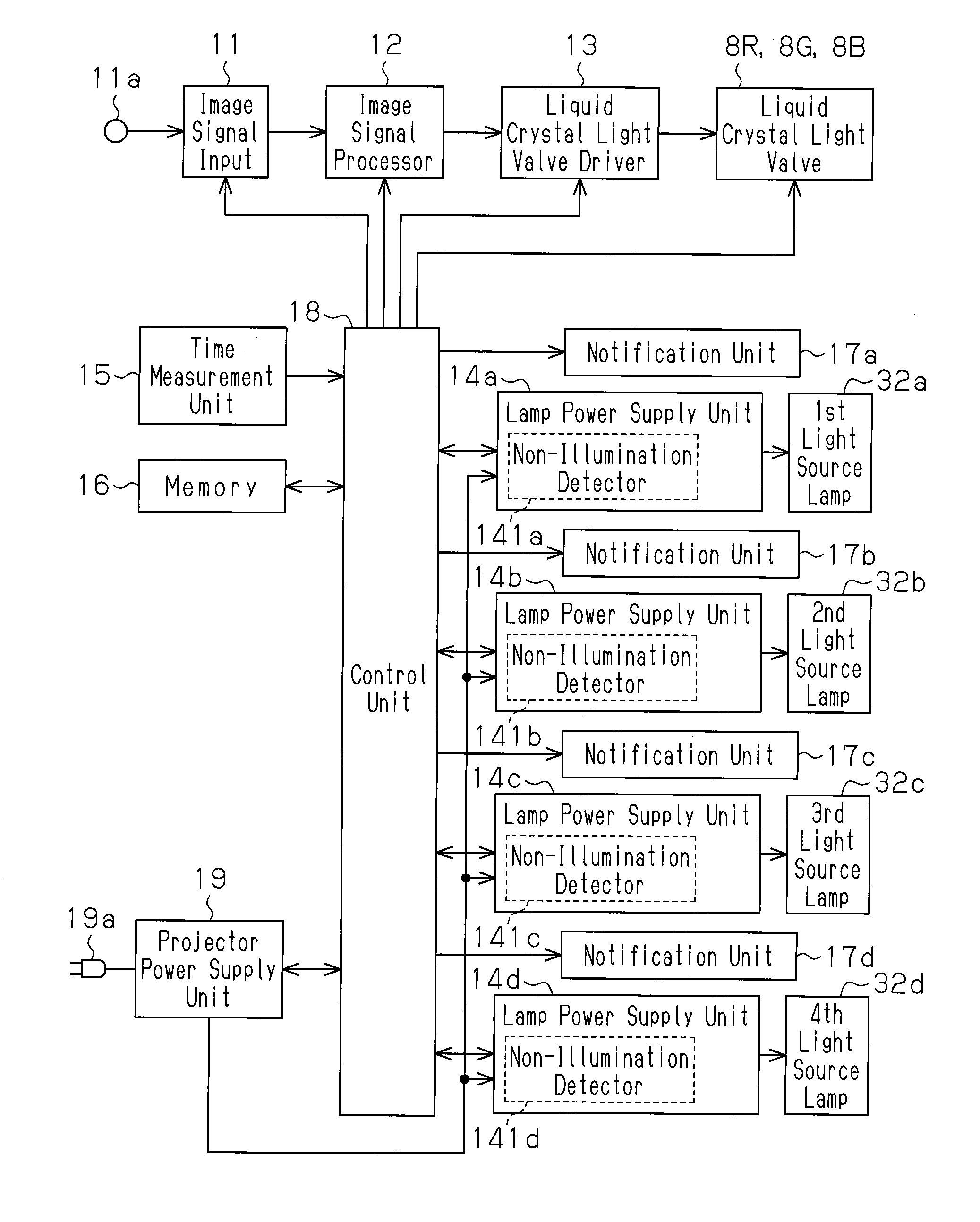
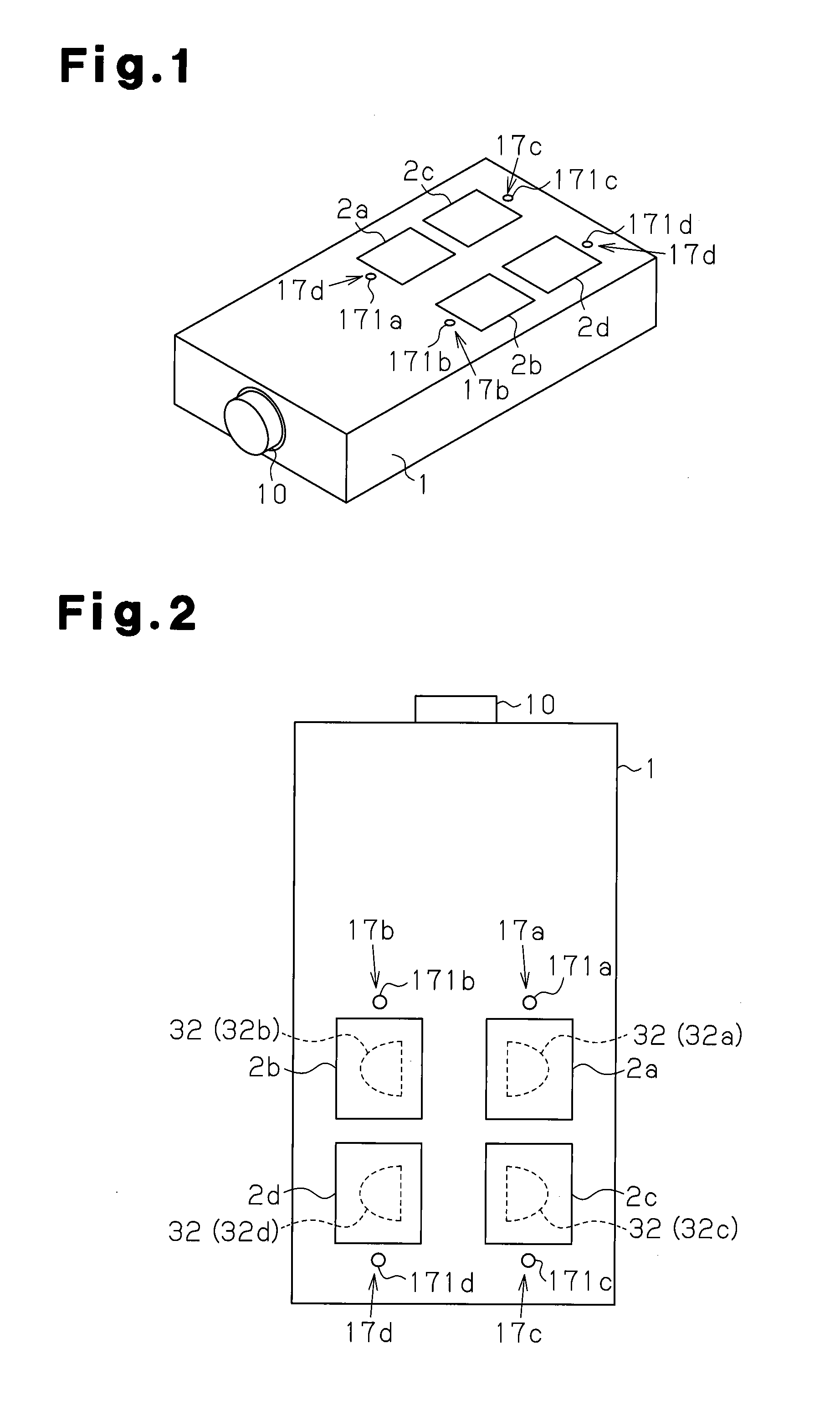
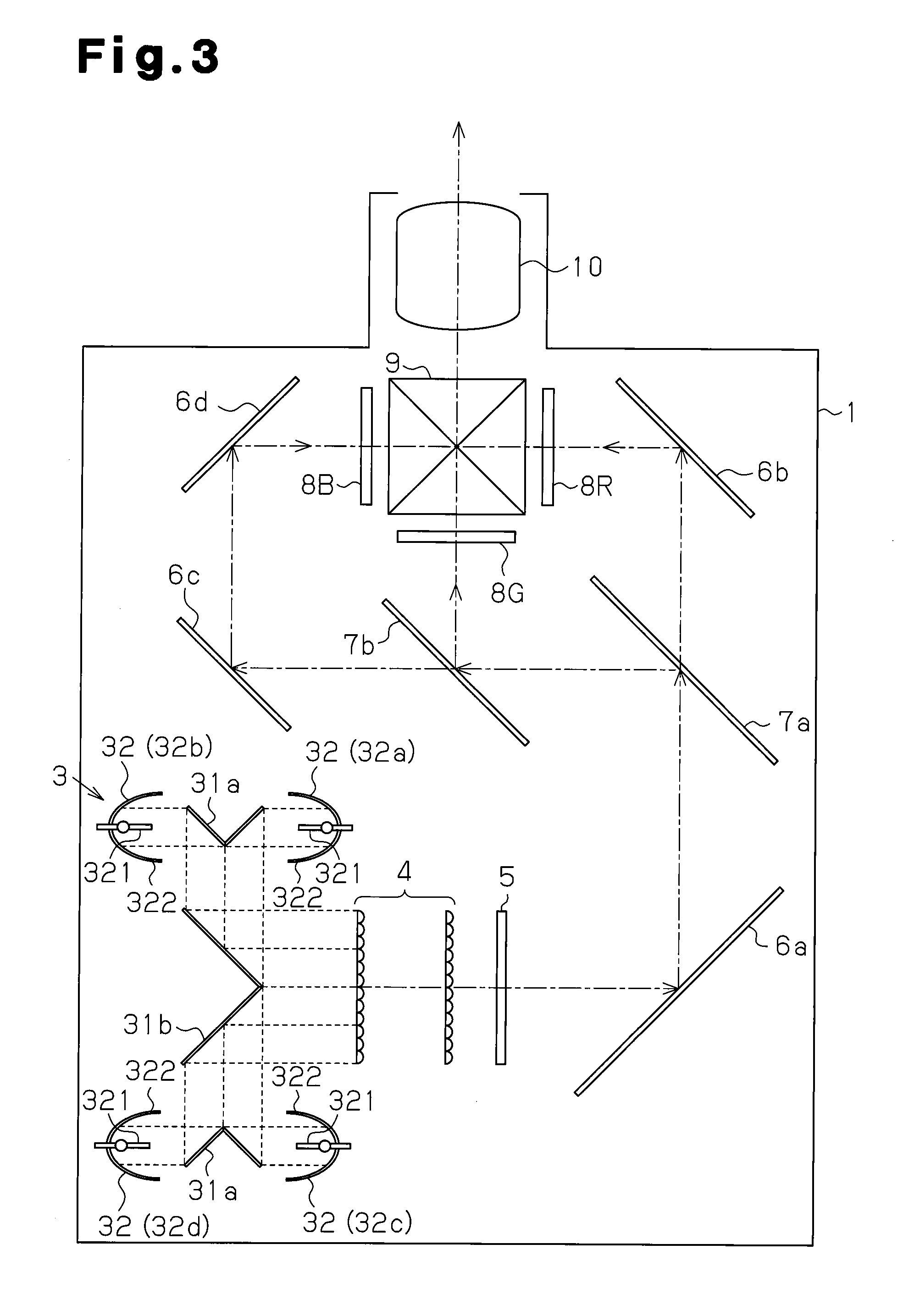
[0020]FIG. 1 shows a state in which the video projector is held upright. As shown in FIGS. 1 and 2, the video projector includes a shell case 1 and a projection lens 10. Lamp covers 2a to 2d for light source lamps 32 are arranged on an upper surface of the shell case 1. Each of the lamp covers 2a to 2d serves as a lid that closes a service port used when replacing the corresponding light source lamp 32. As shown in FIG. 2, the four lamp covers 2a to 2d are respectively arranged in correspondence with four light source lamps 32a to 32d. For example, when replacing the light source lamp 32a, a user opens the lamp cover 2a corresponding to the light source lamp 32a to access the light source lamp 32a through the corresponding service port. In the description hereafter, the state of FIG. 1 will be used as a frame of reference when referring to a vertical dire...


PUM


Abstract

A video projector including replaceable light source lamps, a case that accommodates the light source lamps, lamp covers respectively corresponding to the light source lamps, a time measurement unit that measures an accumulated illumination time of each of the light source lamps, a control unit that determines whether or not the measured accumulated illumination time is greater than a replacement determination time, and notification units respectively corresponding to the light sources. Each notification unit is illuminated, when it is determined that the accumulated illumination time of the corresponding light source lamp is greater than the replacement determination time, to indicate where the corresponding lamp cover is located.

Description

CROSS-REFERENCE TO RELATED APPLICATIONS[0001]This application is based upon and claims the benefit of priority from prior Japanese Patent Application No. 2010-098046, filed on Apr. 21, 2010, the entire contents of which are incorporated herein by reference.BACKGROUND OF THE INVENTION[0002]The present invention relates to a video projector, and more particularly, to a video projector including a notification unit that notifies a user of the necessity to replace a light source lamp.[0003]A discharge type light source lamp, such as an ultra-high pressure mercury lamp or a metal halide lamp, is used as a light source lamp of a video projector. The luminance of a discharge type light source lamp gradually decreases as its usage time (illumination time) becomes longer. Continuous use of a discharge type light source lamp lowers the quality of images displayed by the video projector and illumination of the light source lamp may become difficult.[0004]There are video projectors in the prior...

Claims


Application Information

Patent Timeline
Patent Type & Authority Applications(United States)
IPC IPC(8): H04N5/64
CPCG02B27/1046G02B27/106G02B27/143G02B27/145G02B27/149G03B21/206G03B21/14H04N9/3164G03B21/2013G03B21/2026G03B21/2066G02F1/133621G03B21/145
Inventor KOTANI, KAZUNORI
Owner SANYO ELECTRIC CO LTD
Why Eureka
Try Eureka