Rotor blade and method for producing same

a technology of rotor blades and flanges, applied in the field of rotor blades, can solve the problems of flanges and webs themselves being endangered by bulges, achieving sufficient resistance to bulges, and so on, and achieves the effects of reducing width, less material, and increasing buckling resistance of rotor blades

Active Publication Date: 2011-10-27
SIEMENS GAMESA RENEWABLE ENERGY SERVICE GMBH
View PDF1 Cites 7 Cited by
  • Summary
  • Abstract
  • Description
  • Claims
  • Application Information

AI Technical Summary

Benefits of technology

[0007]As regards the rotor blade the problem is solved by an initially cited rotor blade with at least one flange whose width decreases in accordance with the invention along the longitudinal direction. As a result of the decrease in width in accordance with the invention the flange can extend far into the rotor blade tip and its production requires less material.
[0008]The flanges increase the buckling resistance of the rotor blade. Blades that are opposite one another in the inner space of the rotor blade are preferably permanently connected to one another by at least one web that preferably vertically projects from both flanges.

Problems solved by technology

Rotor blades that are so long and substantially hollow have the problem of achieving sufficient resistance to bulges.
The flanges and webs are themselves endangered by bulges.
However, this has the result that the flanges on the one hand cannot be placed into the outermost rotor blade tip and on the other hand much material is needed for the production of the flange strips.

Method used


Image

  • Rotor blade and method for producing same
  • Rotor blade and method for producing same
  • Rotor blade and method for producing same

Examples


Embodiment Construction

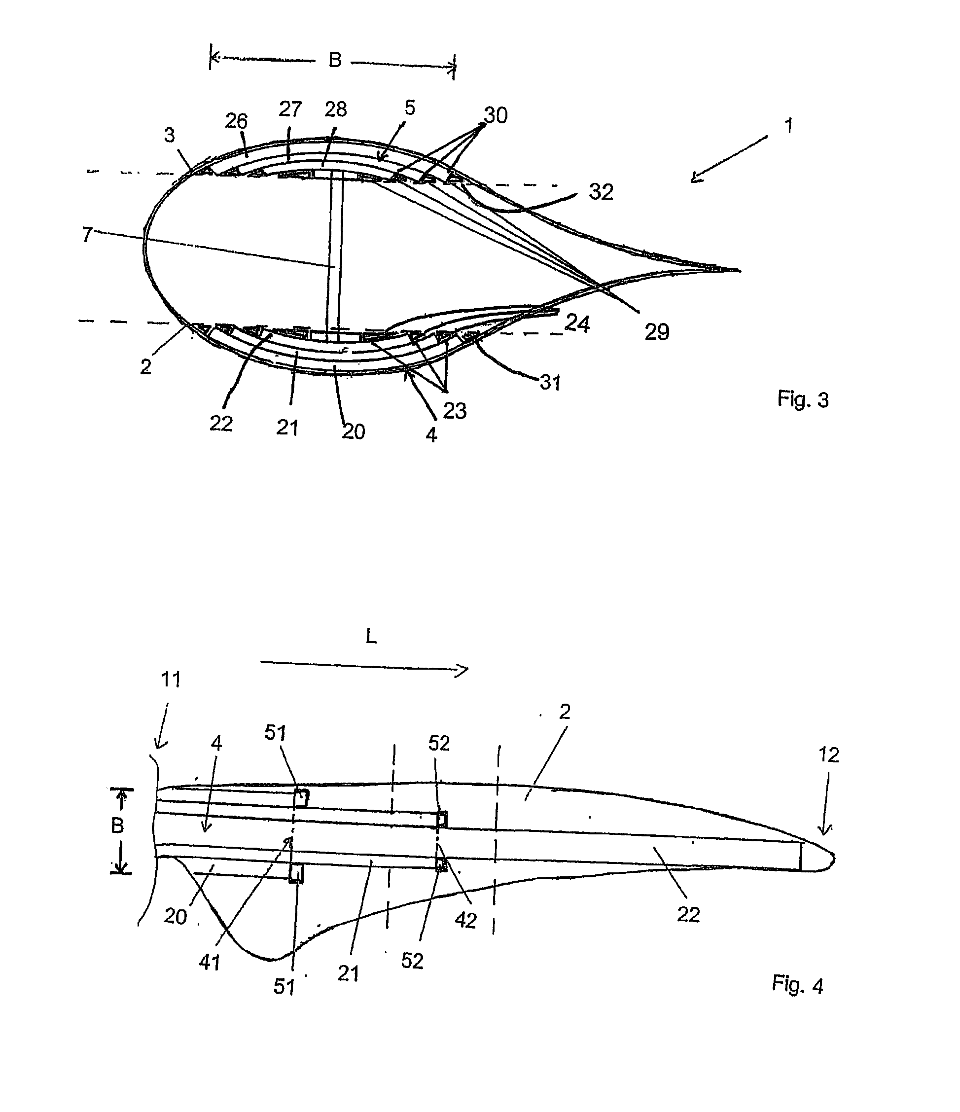
[0015]“Longitudinal direction” denotes here a direction from the rotor blade root toward the rotor blade tip. No distinction is made in the following between a longitudinal direction of the flange, of the rotor blade half skin or of the rotor blade. They should be considered here as coincident.

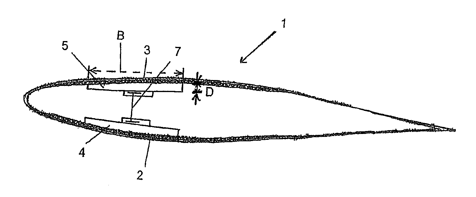
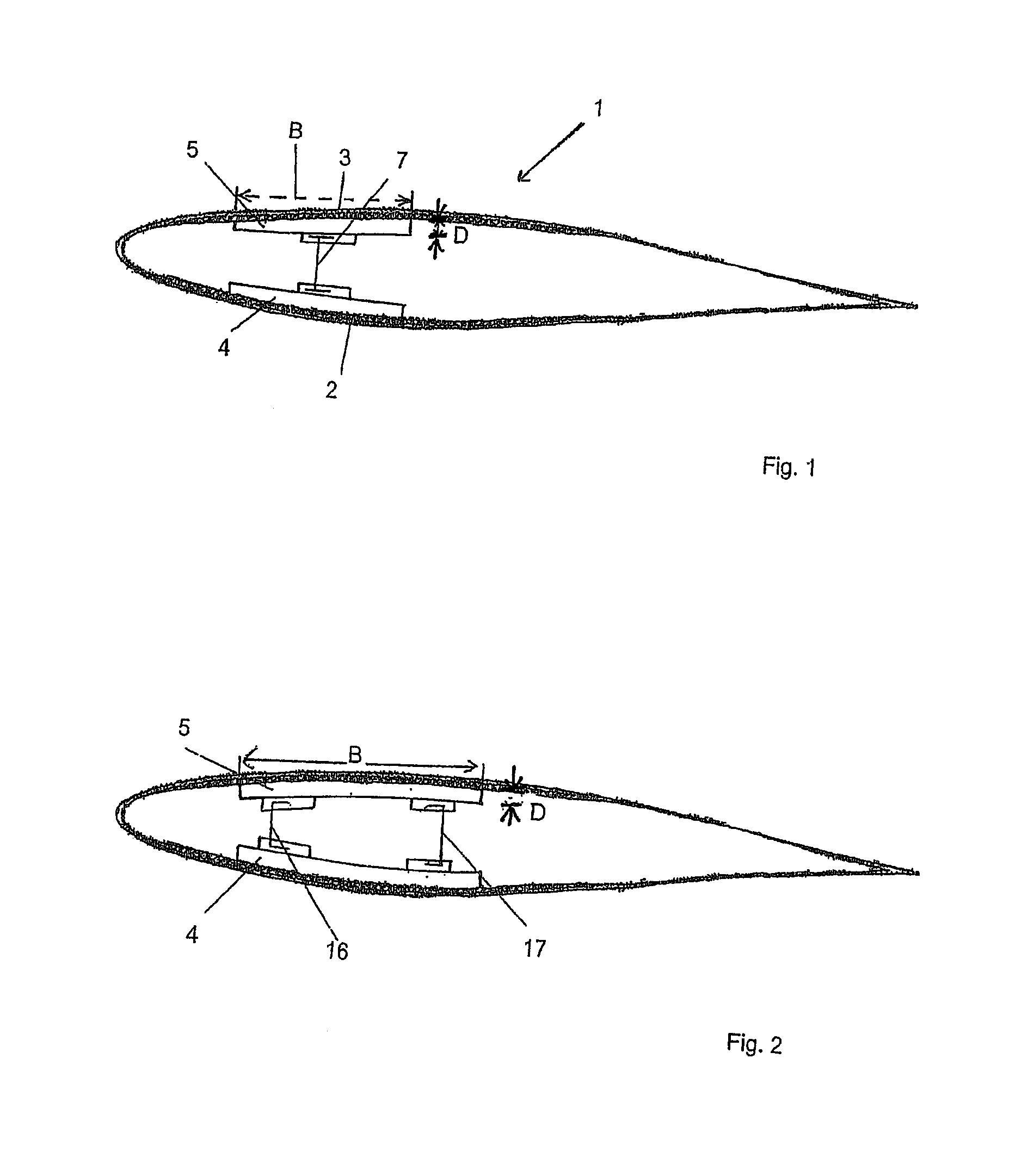
[0016]“The width of the flange” denotes in the following the extent of the flange transversely to the longitudinal direction, preferably vertically to the longitudinal direction. “Transverse direction” also denotes a direction transverse to the longitudinal direction, preferably vertically to the longitudinal direction.

[0017]Experience has shown that rotor blade blades area endangered by bulges in particular in the area of the rotor blade root. Therefore, in order to increase the buckling resistance, flanges which are especially wide along the inner rotor blade sections are necessary. “Outer” and “inner” denote here and in the following the position of the rotor blade section or of the particu...


PUM

PropertyMeasurementUnit
lengthsaaaaaaaaaa
heightaaaaaaaaaa
widthaaaaaaaaaa

Abstract

The invention relates to a rotor blade for wind energy installation, comprising at least one flange running in a longitudinal direction from a rotor blade root to a rotor blade tip, whereby a width of the flange decreases along the longitudinal direction. The invention also relates to a method for producing a rotor blade in that at least one flange with a width decreasing in the longitudinal direction is applied to a rotor blade inner wall, and to a laying assistance device for positioning strips of the flange.

Description

[0001]This invention is a Section 371 national application based on PCT international application PCT / DE2009 / 001271, filed Sep. 11, 2009, and also claims priority from German application DE 10 2008 049 016.4, filed Sep. 25, 2008, and the contents of both applications are incorporation herein in their entiretyBACKGROUND OF THE INVENTION[0002]The invention relates to a rotor blade for a wind energy system with at least one flange running in a longitudinal direction from a rotor blade root to a rotor blade tip and to a method for producing the rotor blade. The invention also relates to a laying assistance device for positioning strips of the flange of the rotor blade.[0003]Rotor blades are sufficiently known in the state of the art. The rotor blades of modern wind energy systems have lengths of 60 meters and more. The rotor blades can have diameters of several meters, in particular in the section of the rotor blade root. Rotor blades that are so long and substantially hollow have the p...

Claims


Application Information

Patent Timeline
Patent Type & Authority Applications(United States)
IPC IPC(8): F01D5/14B23P15/02
CPCB29C70/30B29L2031/082F03D1/0675Y10T29/49336F05B2280/6003F05C2253/04Y02E10/721F05B2250/292Y02E10/72B29C70/302
Inventor SCHUBERT, MATTHIAS
Owner SIEMENS GAMESA RENEWABLE ENERGY SERVICE GMBH
Why Eureka
Try Eureka