Gaseous fluid vessel propulsion system

Inactive Publication Date: 2011-10-27
ADAMS ROBERT D
View PDF6 Cites 13 Cited by
  • Summary
  • Abstract
  • Description
  • Claims
  • Application Information

AI Technical Summary

Benefits of technology

[0004]The object of the present invention is to overcome the disadvantages and limitations of submerged, ducted propulsion systems by creating a water surface-piercing propeller environment within the duct, enclosure, or hull enclosure in which the propeller is operating; an

Problems solved by technology

This may seem counter-productive when compared to the operation of a conventional ducted system which normally has a larg

Method used


Image

  • Gaseous fluid vessel propulsion system
  • Gaseous fluid vessel propulsion system
  • Gaseous fluid vessel propulsion system

Examples


Embodiment Construction

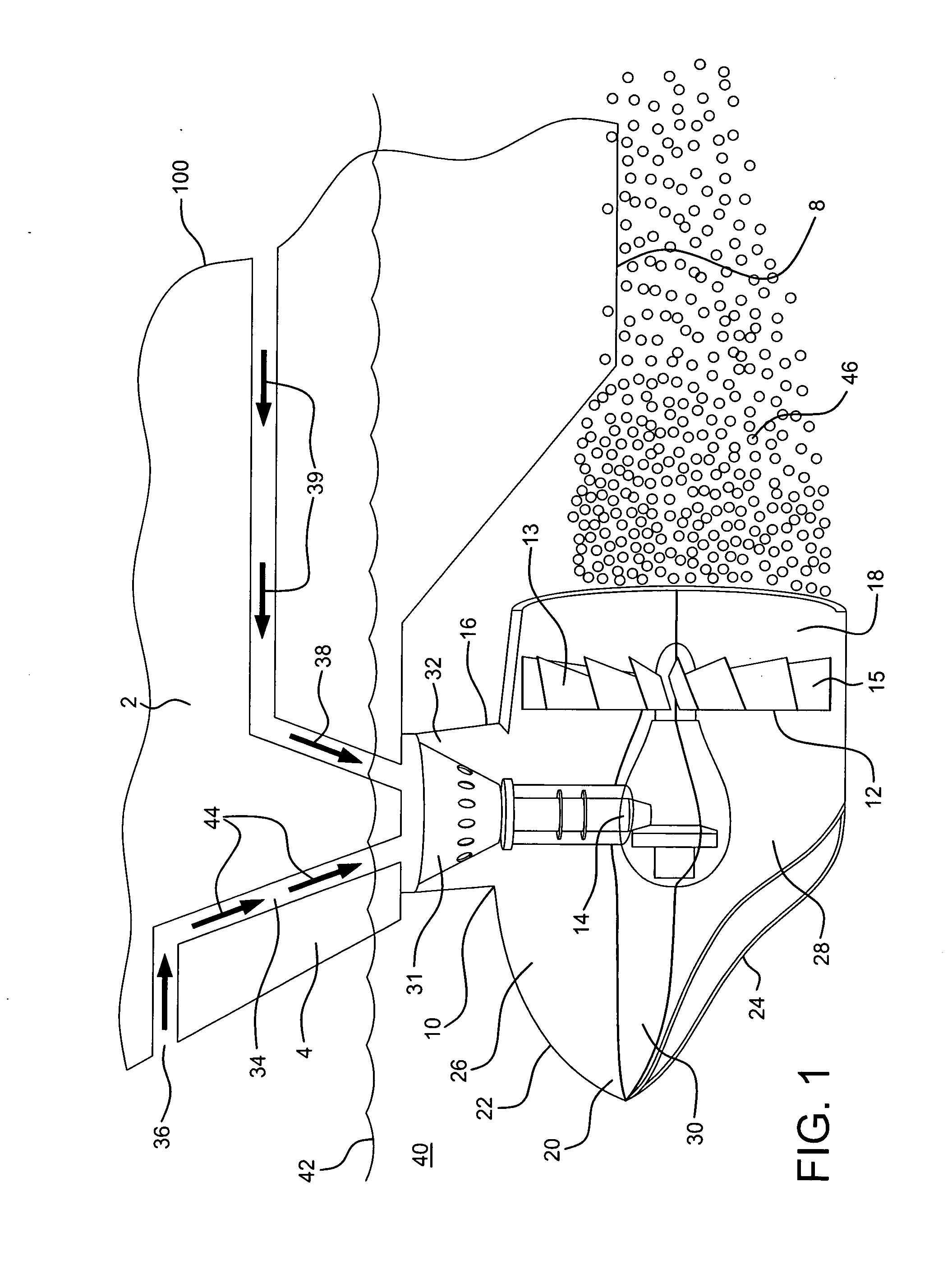
[0020]With particular reference to FIG. 1, waterborne vessel 100 comprises hull 2 having bow 4, stern 6, and hull bottom 8. Propulsion unit 10 extends down from bottom 8 at bow 4 of hull 2. The entire propulsion unit 10 shown in FIG. 1 is configured to be operational below waterline 42 when vessel 100 is moving in a forward direction 42 over body water 40.

[0021]Propulsion unit 10 comprises propeller 12, having a plurality of blades, operable via well known propulsion gearing 14 by the engine of vessel 100. Propeller 12 is housed or enshrouded within and circumscribed by rearward duct section 18 of propeller enclosure or duct 16. Duct 16 also comprises forward duct section 20 whose top portion 22 has a bulbous-type shape and whose bottom portion 24 gently slops downward and merges into the bottom of rearward section 18 of duct 16. Duct 16 is separated into upper duct section 26 and lower duct section 28 by transverse plate 30 which extends across the width of the duct. Duct 16 is sup...


PUM


Abstract

A bow mounted gaseous fluid vessel propulsion system provides for the introduction of gaseous fluids, e.g. ambient air and/or exhaust fluid gas from the vessel's engine, into the enclosure or duct which houses or circumscribes the propeller. Air and other fluid gases are drawn down into the upper section of the enclosure or duct to allow the propeller to operate in a half submerged, or water surface-piercing condition, while the vessel is moving forward through the water. The beneficial effects of water surface-piercing propeller operation is thereby obtained within a self-contained unit which continually maintains the top of the propeller out of the water during normal forward vessel operation.

Description

BACKGROUND OF THE INVENTION[0001]Important benefits are realized by the utilization of bow mounted surface-piercing propeller systems, both on large displacement vessels such as ships and barges, and on more streamlined, lower displacement, high speed watercraft. Most significant of these benefits is the production of the self-producing, lubricating boundary layer of gaseous fluid, e.g. air and air bubbles created by the intermixing by the rotating bow propeller of water and air. This layer of gaseous bubbles, produced during forward vessel motion, travels over the bottom surface of the vessel, thus reducing frictional drag on the vessel's hull as it moves through the water. This significant benefit of bow mounted surface-piercing propellers, as well as others, are described in detail in U.S. Pat. No. 7,096,810, the relevant disclosure of which is incorporated by reference herein.[0002]It is accepted that vessel thrust and thus vessel efficiency will be increased by the use of a pro...

Claims


Application Information

Patent Timeline
IPC IPC(8): B63H5/15B63B1/38
CPCB63B1/38Y02T70/122B63H5/07Y02T70/10
Inventor ADAMS, ROBERT D.
Owner ADAMS ROBERT D
Why Eureka
Try Eureka