
Switchable free-wheel arrangement for a transmission, particularly for a crank-CVT of a motor vehicle

a technology of free-wheel arrangement and transmission, which is applied in the direction of freewheel clutches, toothed gearings, belts/chains/gearrings, etc., can solve the problems of extreme space-saving clamping body arrangement, and achieve the effect of simple design, small diffusion of clamping body resiliency force, and cost reduction

Inactive Publication Date: 2011-10-27
SCHAEFFLER TECH AG & CO KG
View PDF25 Cites 2 Cited by
  • Summary
  • Abstract
  • Description
  • Claims
  • Application Information

AI Technical Summary

Benefits of technology

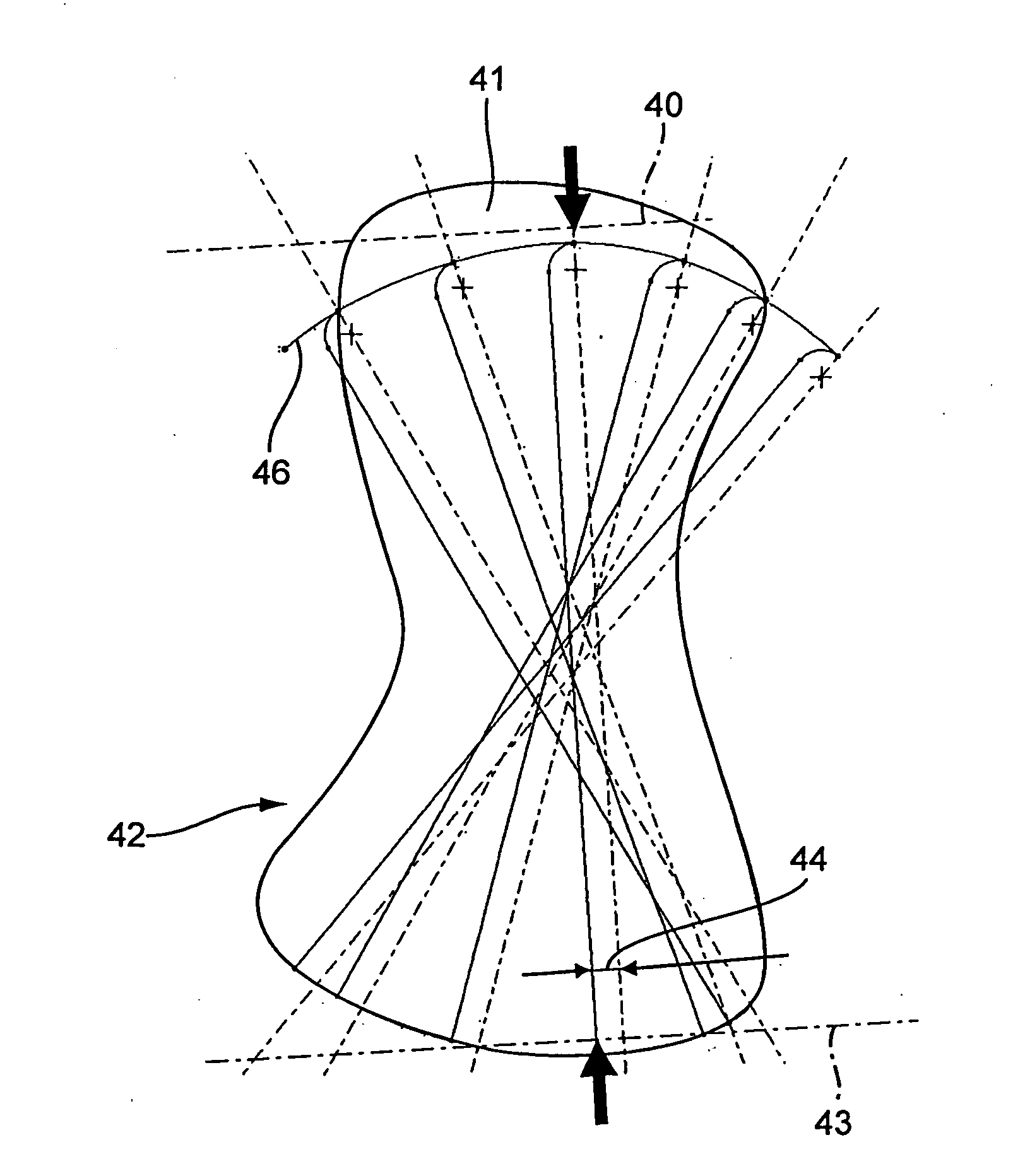
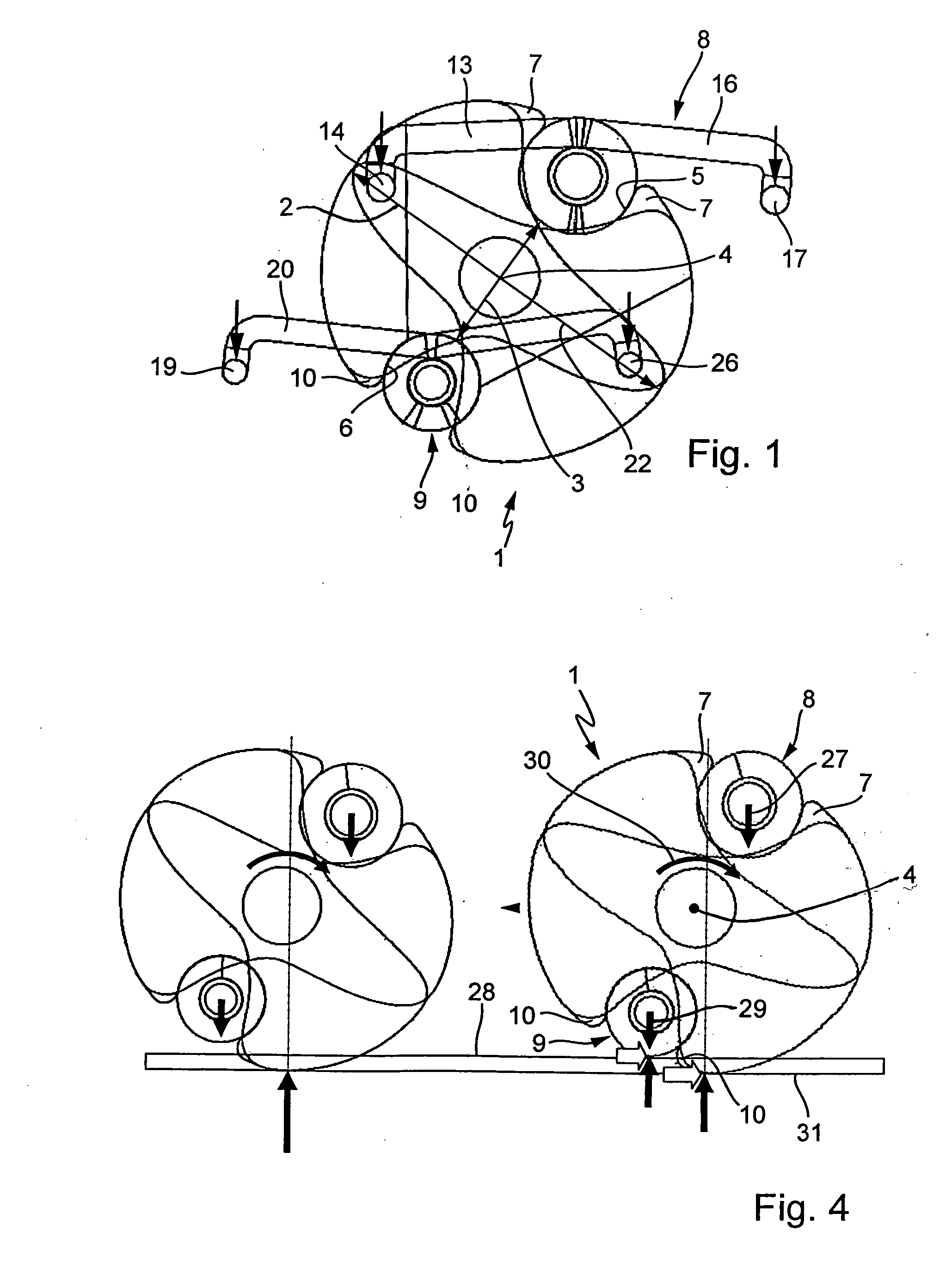
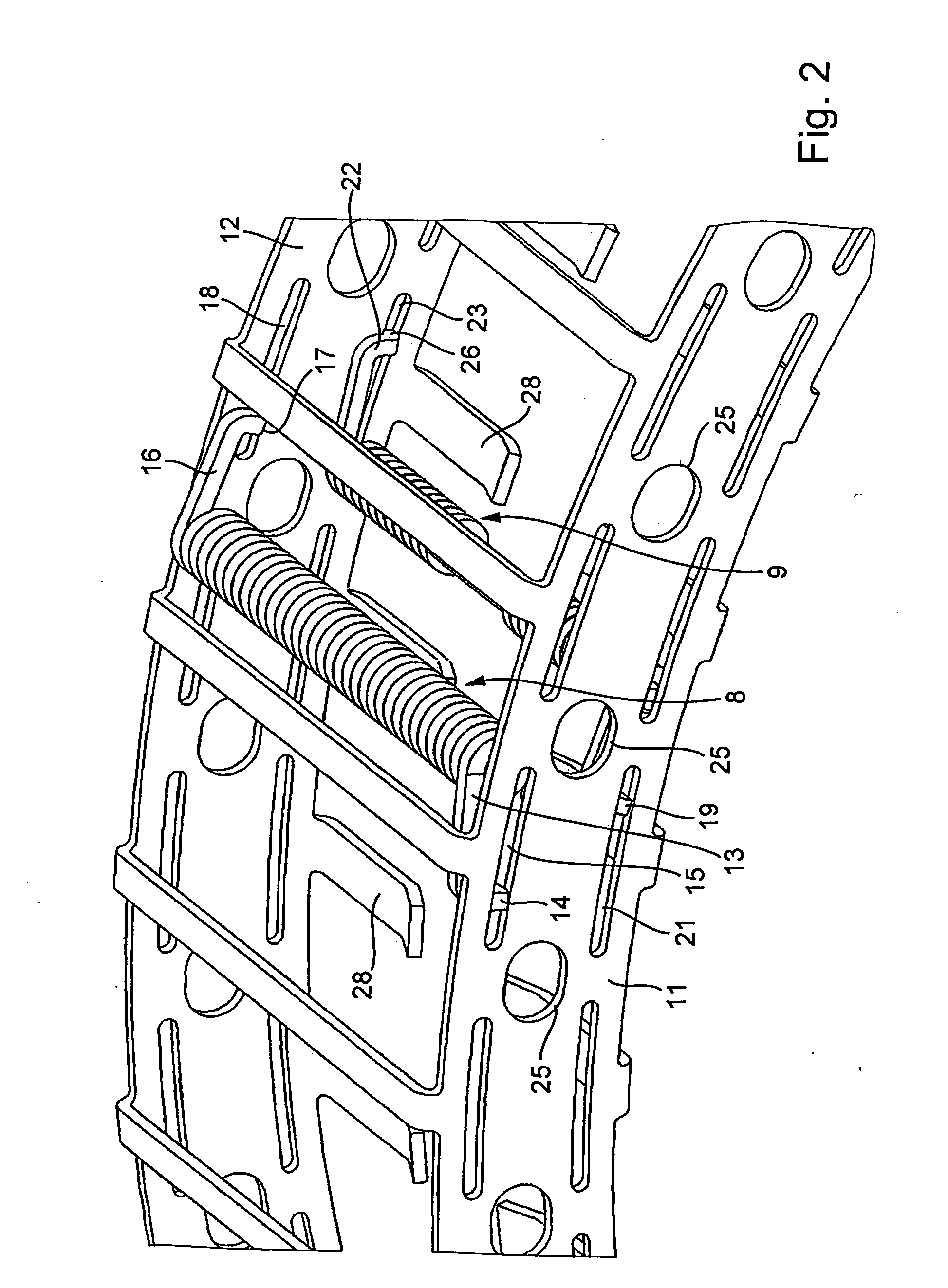
The present invention relates to a switchable freewheel device for a transmission, particularly for a crank CVT of a motor vehicle. The invention provides a clamping body that can be pressed against the inner ring by an energy accumulator, and a switching mechanism that can be used to set the clamping body in either the release or clamping direction. The energy accumulator includes two torsion springs that produce set-up force in opposite directions, resulting in a small detachment force. The clamping body has cylindrical recesses that hold the torsion springs, and the end sections of the torsion springs are fitted in elongated holes in the cage. The clamping body has a cross-section with a larger diameter and a smaller diameter, and the recesses are positioned in the sections of the clamping body that do not get in contact with the inner and outer rings during operation. The cage can also include limit stops for the clamping bodies. The invention provides a space-saving clamping body arrangement and reduces the cost of the freewheel device. The use of a worm spring as the energy accumulator provides a more advantageous diffusion of the resiliency force and a longer service life.

Problems solved by technology

This results in an extremely space-saving clamping body arrangement.

Method used


Image

  • Switchable free-wheel arrangement for a transmission, particularly for a crank-CVT of a motor vehicle
  • Switchable free-wheel arrangement for a transmission, particularly for a crank-CVT of a motor vehicle
  • Switchable free-wheel arrangement for a transmission, particularly for a crank-CVT of a motor vehicle

Examples


Embodiment Construction

[0023]The following considerations led to the invention. If one strongly presses the clamping bodies for the generation of a relatively high friction between the clamping bodies and the inner ring of the freewheel device, through a strong spring force against the inner ring, one must provide that the force for setting up the clamping bodies into the release- or clamping direction becomes relatively small. This can be achieved in that either for a large lever arm for the generation of the set-up force two torsion springs are used, of which the torque magnitudes act in different directions, whereby the torque difference that is decisive for setting up the clamping bodies is relatively small. The frictional forces developed by the two torsion springs add up nonetheless.

[0024]In the case, in which the high frictional force is generated by a worm spring, the torque can be generated by a very small lever arm, which is held constant over the entire clamping process. This can be ensured by ...


PUM


Abstract

A switchable free-wheel arrangement for a CVT transmission of a motor vehicle. Clamping bodies held in a cage are disposed between an outer ring and an inner ring. Each clamping body can be pressed with a relatively high force against the inner ring by an energy accumulator. The clamping bodies can be set up in the release direction or in the clamping direction by a switching mechanism. The energy accumulator generates a relative small setup force for setting up the clamping bodies. The energy accumulator includes two torsion springs disposed on the clamping body. It can, however, also have the shape of a helical spring that surrounds the clamping bodies and engages therein in special helical spring grooves.

Description

BACKGROUND OF THE INVENTION[0001]1. Field of the Invention[0002]The present invention relates to a freewheel arrangement for a transmission, particularly for a crank CVT of a motor vehicle.[0003]2. Description of the Related Art[0004]DE 102 43 535 A1 discloses a continuously variable transmission that includes an input shaft and an output shaft that are supported, rotatably aligned parallel to each other in a transmission. Both shafts are connected with one another via an eccentric device of the input shaft and a freewheel device disposed on the output shaft, as well as by a connection device connecting the eccentric device and the freewheel device. The eccentric device includes several eccentric units that are disposed axially next to one another on the input shaft. The freewheel device includes several freewheel units that are disposed axially next to one another on the output shaft. To form each eccentric unit, the input shaft includes a guide section eccentrically offset with re...

Claims


Application Information

Patent Timeline
Patent Type & Authority Applications(United States)
IPC IPC(8): F16H3/44
CPCY10T74/19251F16D41/084F16D2041/0603
Inventor M N, LASZLO
Owner SCHAEFFLER TECH AG & CO KG
Learn More