Wheel hub transmission unit for a drive wheel of a vehicle, drive wheel, and vehicle having an auxiliary drive

a technology of transmission unit and drive wheel, which is applied in the direction of instruments, cycles, transportation and packaging, etc., can solve the problems of difficult cabling of coil pair and disadvantageous installation space of measuring sleeves, and achieve the effect of simple construction

Active Publication Date: 2018-07-03
FAZUA GMBH
View PDF24 Cites 2 Cited by
  • Summary
  • Abstract
  • Description
  • Claims
  • Application Information

AI Technical Summary

Benefits of technology

[0006]An object of the invention is to provide a wheel hub transmission unit for a drive wheel of a vehicle, a drive wheel with the wheel hub transmission unit, and a vehicle having an auxiliary drive with the drive wheel, the wheel hub transmission unit being of simple construction and space-saving.
[0013]As a result of the fact that the annular space is axially accessible from outside the transmission sleeve on account of the mounting of the transmission sleeve in a cantilever manner by way of the radial bearing, the cabling for the inner sensor coil at the second longitudinal end is advantageously to be guided to the outside of the transmission sleeve, and no additional passages for the cabling are needing to be provided in the wheel axle. The construction of the wheel hub transmission unit is therefore advantageously simple. Moreover, the transmission sleeve is advantageously of short configuration, although the measuring area is provided to be sufficiently long for the required measuring accuracy. The installation space of the wheel hub transmission unit is therefore advantageously small, with the result that the wheel hub transmission unit can be integrated easily into the drive wheel.
[0014]According to an aspect of the invention, the output coupling arrangement centers the second longitudinal end of the transmission sleeve about the wheel axle during the transmission of the torque. This advantageously achieves a situation where, although the transmission sleeve is mounted at the first longitudinal end in a cantilever manner by way of the radial bearing, the transmission sleeve nevertheless runs smoothly at the second longitudinal end in the case of corresponding mechanical loading during the transmission of the torque. The mechanical bending fatigue loading of the transmission sleeve during the transmission of the torque is therefore advantageously low. Moreover, corresponding non-round running of the transmission sleeve at the second longitudinal end would have the consequence of a falsification of the torque magnitude which is measured in the measuring area by way of the sensor coil. The centering action of the output coupling at the second longitudinal end counteracts this, with the result that the torque transmission device has a high measuring accuracy.
[0016]According to an aspect of the invention, the pinion hub carrier is preferably a sleeve which covers the measuring area of the transmission sleeve to the outside. As a result, the measuring area is protected to the outside by the transmission sleeve, and the measuring area is not subjected, for instance, to damaging environmental influences, such as dirt or jolts, for example. Moreover, the pinion hub carrier is given a length which is so large that a plurality of pinions can be satisfactorily accommodated on the pinion hub carrier so as to lie next to one another. Furthermore, according to another aspect of the invention, the outer side of the pinion hub carrier has a splined shaft profile which is formed by grooves and webs which run alternately parallel to the wheel axle. The pinion has a hub which is shaped correspondingly in a negative manner with respect to the splined shaft profile, with the result that the pinion can be mounted in a torsionally rigid manner on the pinion hub carrier in a positively locking manner in the circumferential direction.
[0019]A stable and compact overall design of the drive coupling arrangement is achieved by way of the abovementioned example embodiments of the drive coupling arrangement, the radial bearing being provided in the axial extent region of the drive coupling arrangement between the inner side of the transmission sleeve and the wheel axle. As a result of the alignment of the radial bearing with the threads or the locating fit, an optimum power flow is achieved during the transmission of the torque from the drive coupling to the output coupling. The torque is transmitted from the pinion to the pinion hub carrier via the threads or the locating fit and the end face and via the axial block to the transmission sleeve, the measuring area of the transmission sleeve protruding immediately axially from the radial bearing and the drive coupling arrangement. As a result, twisting of the measuring area is made possible during the transmission of the torque, without a bending moment which would impair the torque measurement being exerted on the transmission sleeve.
[0020]The axial block is preferably configured as one piece with the pinion hub carrier. As a result of the fact that the axial block radially protrudes to the inside on the pinion hub carrier and the threads are configured on the transmission sleeve and the pinion hub carrier, an assembly which is stable in the axial direction and radial direction between the pinion hub carrier and the transmission sleeve is achieved by the drive coupling arrangement and by way of the screw connection of the threads and the bearing of the end face of the first longitudinal end against the axial block. During the transmission of the torque from the pinion hub carrier via the drive coupling arrangement to the transmission sleeve, no disruptive warping and stress unevennesses, for instance, are transmitted from the drive coupling arrangement to the measuring area. Therefore, the measuring area can immediately adjoin the drive coupling arrangement, that is the radial bearing and the threads of the locating fit, as a result of which, for instance, transitions for attenuating stress peaks in the measuring area do not need to be provided. As a result, the overall length of the transmission sleeve can be kept low, although the measuring area is provided in its necessary axial length. Moreover, the measuring area can be guided as far as the output coupling arrangement, as a result of which any transitions for reducing warping and stress unevennesses between the output coupling arrangement and the measuring area do not need to be provided there either.

Problems solved by technology

This results in the problem that the cabling of the coil pair is difficult and the measuring sleeve disadvantageously requires a large amount of installation space at the hub.

Method used


Image

  • Wheel hub transmission unit for a drive wheel of a vehicle, drive wheel, and vehicle having an auxiliary drive
  • Wheel hub transmission unit for a drive wheel of a vehicle, drive wheel, and vehicle having an auxiliary drive

Examples


Embodiment Construction

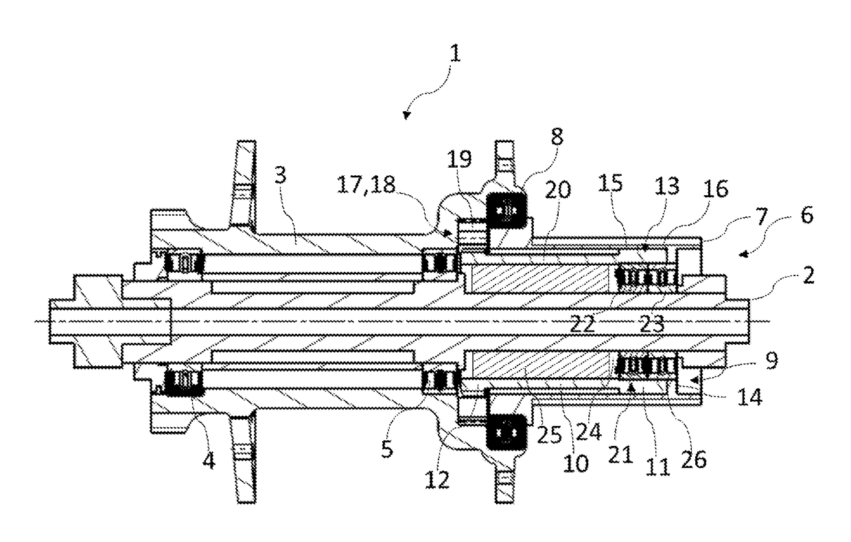
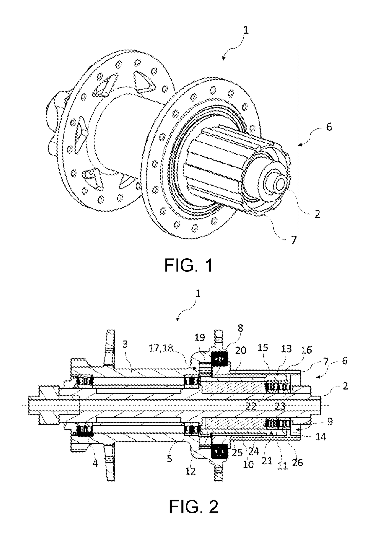
[0026]FIGS. 1 and 2 show a wheel hub 1 which has a wheel axle 2 and a hub body 3. The hub body 3 is mounted on the wheel axle 2 such that it can be concentrically rotated about the wheel axle 2 by a first wheel hub bearing 4 and a second wheel hub bearing 5.

[0027]The wheel axle 2 completely axially extends through the wheel hub body 3, the first wheel hub bearing 4 being arranged at the one longitudinal end of the wheel hub body 3 and the second wheel hub bearing 5 being arranged at the other longitudinal end of the wheel hub body 2. Two flat rings which are arranged at an axial spacing from one another are provided on the wheel hub body 3, into which flat rings spokes can be hooked.

[0028]Furthermore, the wheel hub 1 has a wheel hub transmission unit 6 which is laterally arranged about the wheel axle 2 next to the second wheel hub bearing 5 and on the other side of the first wheel hub bearing 4. The wheel hub transmission unit 6 has a pinion hub carrier 7 which is configured as a sl...


PUM

PropertyMeasurementUnit
axial distanceaaaaaaaaaa
torqueaaaaaaaaaa
areaaaaaaaaaaa

Abstract

A wheel hub transmission unit for a drive wheel of a vehicle is provided. The wheel hub transmission unit includes a wheel axle, a pinion hub carrier concentrically arranged with respect to the wheel axle, a pinion mounted in a torsionally rigid manner onto said pinion hub carrier and configured to drive the drive wheel, and a torque transmission device having a transmission sleeve. The transmission sleeve is made from a magnetically coded material and includes a measuring area that is utilized to measure a torque by utilizing magnetic properties of the magnetically coded material of the transmission sleeve. An annular space is radially provided between the transmission sleeve and the wheel axle in the measuring area with a sensor coil being accommodated therein, the annular space being axially accessible from outside the transmission sleeve.

Description

CROSS REFERENCE TO RELATED APPLICATIONS[0001]This application is a continuation application of international patent application PCT / EP2014 / 067617, filed Aug. 19, 2014, designating the United States and claiming priority from European application 13181730.6, filed Aug. 26, 2013, and the entire content of both applications is incorporated herein by reference.FIELD OF THE INVENTION[0002]The invention relates to a wheel hub transmission unit for a drive wheel of a vehicle, to a drive wheel with the wheel hub transmission unit, and to a vehicle having an auxiliary drive with the drive wheel.BACKGROUND OF THE INVENTION[0003]Electrically driven vehicles are gaining more and more importance for meeting different individual mobility requirements. In particular, the electric bicycle is on the rise. An electric bicycle is a bicycle having an electric motor as an auxiliary drive. An electric drive assistance is conventionally requested by way of pedaling pedals which are fastened to the pedal c...

Claims


Application Information

Patent Timeline
Patent Type & Authority Patents(United States)
IPC IPC(8): B60B27/02B60B35/12F16D41/12G01L3/10F16D41/24B62M6/50B62M6/60B60B27/00
CPCB62M6/60B60B27/0026B60B27/023B60B35/121F16D41/12G01L3/104B62M6/50B60Y2200/13B60B2900/115
Inventor PIELE, THEODOR
Owner FAZUA GMBH
Why Eureka
Try Eureka