Inductive power transfer system

a power transfer system and inductive power technology, applied in the direction of exchanging data chargers, circuit arrangements, electrical equipment, etc., can solve the problems of complex connector extraction mechanisms or explosive charges, damage to vehicle systems, and potential problems in environments, so as to achieve faster and more accurate response, reduce errors, and reduce complexity

Active Publication Date: 2020-04-30
MBDA UK
View PDF0 Cites 2 Cited by
  • Summary
  • Abstract
  • Description
  • Claims
  • Application Information

AI Technical Summary

Benefits of technology

[0011]Such a system provides an improved power transfer system compared to the systems of the prior art and in particular over a system utilising an infra-red feedback mechanism. The present system feeds back from the secondary to the primary unit using circuitry which is advantageously small and inexpensive compared to infra-red emitter and receiver components. Furthermore, the present system is likely to produce a faster and more accurate response, not requiring infra-red transmission across the air gap, thus minimising errors arising from fluctuations in air pressure and temperature. The system of the present invention advantageously does not need more than one interface between the primary and secondary units, the interface used for both power transfer and feedback. In a further advantage over the prior art, the present system may allow for some adjustment of a frequency of the source (i.e. drive) signal to help maintain efficiency as the air gap, temperature or other variables alter during operation.

Problems solved by technology

Timing of the disconnection is critical in such applications and the use of complex connector extraction mechanisms or an explosive charge, however small, in such environments is potentially problematic.
This is because forces resulting from the mechanical uncoupling or explosion may adversely affect the planned trajectory of the newly launched vehicle or may cause damage to the vehicle systems.
There are many other applications where conventional energy transmission systems, using cables and connectors, present difficulties or are not feasible.
These devices typically incorporate “secondary” power cells which can be recharged via inductive coupling rather than direct electrical connection, saving the user the cost and inconvenience of regularly having to purchase new cells.
However, the regulation of inductive power transfer systems can be problematic.
If insufficient power is induced in the secondary (the receptor), the load is starved.
If the transferred power is excessive, surplus current circulates within the secondary unit of the system, over-supplying the load and causing damage, or loss of efficiency by energy ‘dumping’ and the consequential generation of waste heat.
Moreover, due to the thermal constraints and response times associated with electronic components of the system, it is not always practical to continuously apply the maximum power levels to the primary coil so as to transfer maximum power.
Certain problems are associated with the use of infra-red light components, including that the signal can be blocked by foreign material so, for example, the weather (e.g. rain, dust, pollen) can impact the received signal quality, and contamination by dirt or moisture may affect or interfere with correct detection of the feedback signal.
Furthermore, an infra-red system may be subject to external interference causing incorrect decoding of the signal state.

Method used


Image

  • Inductive power transfer system
  • Inductive power transfer system
  • Inductive power transfer system

Examples


Embodiment Construction

High-Level Function

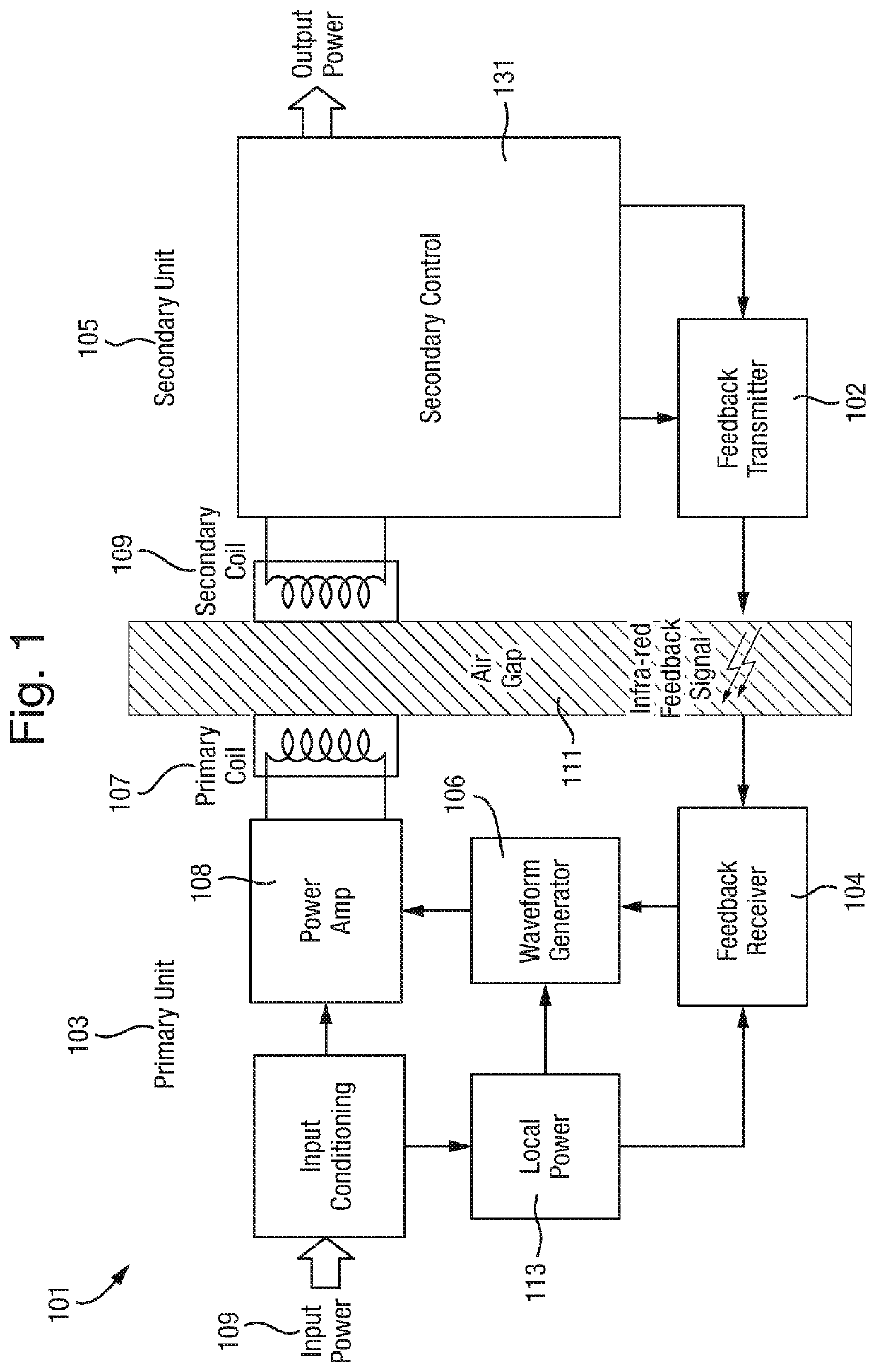
[0050]The present invention is an improvement of the inductive power transfer system disclosed in WO2008 / 017818A1 “the example prior art” (FIG. 1).

[0051]The example prior art inductive power transfer system 101 is designed for use in an aircraft environment. It has a primary power transmitting coil 107 and a secondary power receiving coil 109 separated by an air gap 111. The air gap 111 can be varied between 1mm and 10mm, depending on the physical size of the power transformer and the quantity of power to be transferred.

[0052]The system 101 comprises primary unit components coupled to the primary coil 107 and secondary unit components coupled to the secondary coil 109, with a feedback transmitter 102 and receiver 104 to feed a signal from the secondary unit 105 to the primary unit 103.

[0053]The primary unit 103 includes a single phase or 3-phase alternating current, or direct current power input. The primary unit 103 is carried by the host aircraft (not shown) whi...


PUM


Abstract

An inductive power transfer system (1) for coupling a power source to a load across an air gap (11) is disclosed. The system (1) comprises a primary unit (3) associated with a host platform and a secondary unit (5) arranged to receive power transmitted inductively from the primary unit (3). The primary unit (3) includes a phase detection circuit (21) configured to detect phase changes in a signal in the primary unit (3) indicative of changes in an operating condition within the secondary unit (5), and a drive circuit (17). The drive circuit (17) is configured to adjust the power level transmitted to the secondary unit (5) depending on the detected phase.

Description

FIELD OF THE INVENTION[0001]The present invention concerns inductive power transfer systems, and in particular regulation of power transfer in such power transfer systems.BACKGROUND OF THE INVENTION[0002]Many types of spacecraft and missile systems use an umbilical connector extending between a host and a vehicle to be launched. Such an umbilical connection allows the transfer of power and data between the host and the vehicle prior to launch and must be disconnected when the launch vehicle is mechanically separated from the host. Disconnection is typically achieved by a detachable connector assembly or by the use of small explosive devices that are controllably activated to sever the connection at an appropriate time. Timing of the disconnection is critical in such applications and the use of complex connector extraction mechanisms or an explosive charge, however small, in such environments is potentially problematic. This is because forces resulting from the mechanical uncoupling ...

Claims


Application Information

Patent Timeline
Patent Type & Authority Applications(United States)
IPC IPC(8): H02J50/12
CPCH02J50/12H02J50/80H02J7/00034
Inventor LEEKS, HOWARD MALLORY
Owner MBDA UK
Why Eureka
Try Eureka