
Iontophoretic delivery system

Inactive Publication Date: 2011-10-27
KOPMAN STANLEY E
View PDF3 Cites 3 Cited by
  • Summary
  • Abstract
  • Description
  • Claims
  • Application Information

AI Technical Summary

Problems solved by technology

A typical application period for creation of skin anesthesia is approximately 10-20 minutes, which consumes instrument, caregiver, and patient time.
In these types of systems it is well known that if such a device is improperly loaded, the device will not perform as desired.
A disadvantage to this approach is that the electrodes can be easily over-filled or under-filled.
Therefore, the uses of these devices may require highly trained personnel to be sure a proper amount of medical solution is actually administered.
Unfortunately, this inevitably reduces shelf life.
During storage, moisture emanating from the medicine solution can be absorbed into adjacent materials, resulting in corrosion of metallic components, degradation of power sources, and inadequate hydration of the medicine pad.
Unfortunately, in these systems the electrode is still stored in a wet environment, and is therefore susceptible to corrosive deterioration.
These devices are mechanically complex, and can fail if, for example, the package is squeezed during shipping, the container breaks and fluids are pre-maturely released.
Other failure modes include compromising the fluid delivery path during storage.
For example, if outgassing hydrophobic plasticizer material is absorbed into the fluid channel, this will inhibiting the transfer of fluid at the time of use.

Method used


Image

  • Iontophoretic delivery system
  • Iontophoretic delivery system
  • Iontophoretic delivery system

Examples


first embodiment

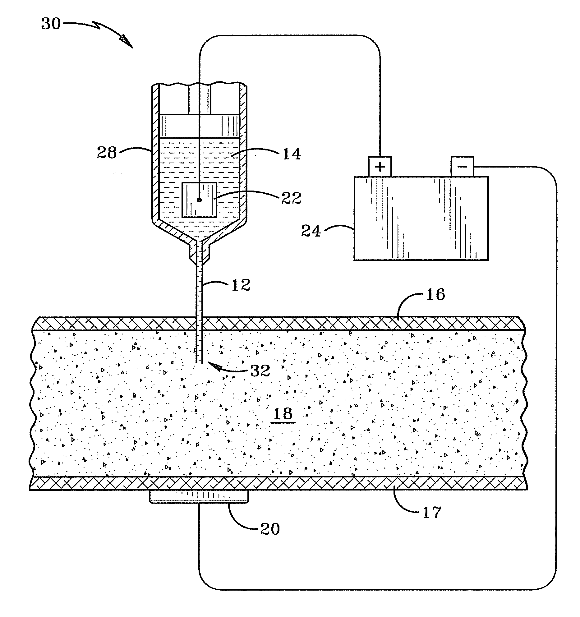
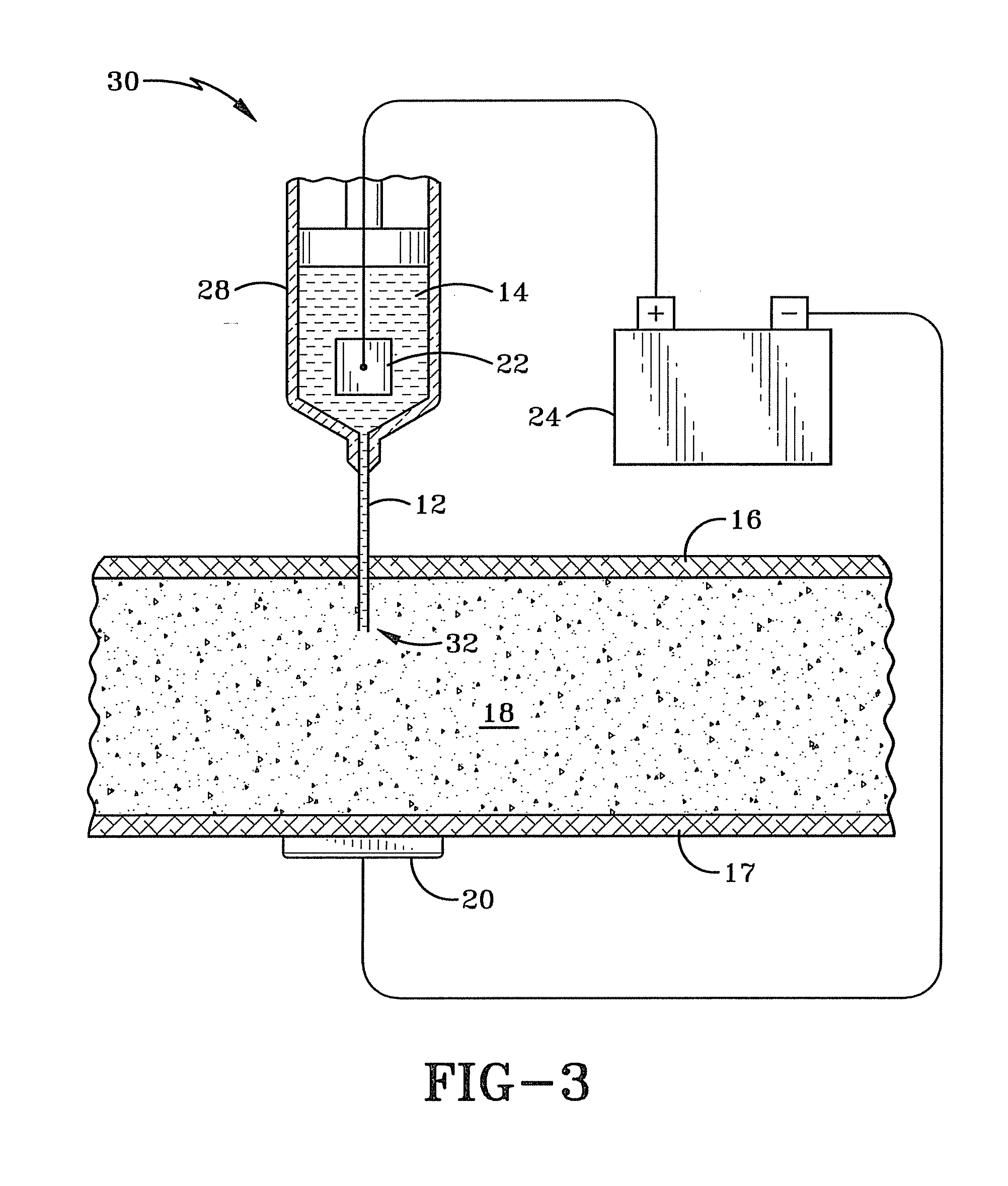
[0019]FIG. 3 illustrates a first embodiment that is the preferred embodiment of a system 30 for iontophoretically administering an iontophoretic medicine. The system 30 improves over the prior art systems discussed earlier by at least partially immersing a submersible electrode 22 into an ionized (e.g. iontophoretic) solution 14 with a medicine and injecting the medicine into body tissue 18 beneath the skin 16. This allows for precise initial placement of the medicine within the body as well as providing a way to control the dosage amount of the medicine entering the body. An ionic current is created between the submersible electrode 22 and another external electrode 20 placed on the surface of the skin 17 on the body. This current will cause the iontophoretic medicine to flow from the injection point 32 toward the external electrode 20. The concentration of the medicine may be increased or decreased by controlling the ionic current with the voltage applied by a power supply 24. The...

second embodiment

[0025]FIG. 4 illustrates a second embodiment that is a method 400 of administering an iontophoretic solution with a medicine. The method 400 applies a voltage across a body tissue and an iontophoretic solution including medicine, at 402. This voltage will cause the iontophoretic transportation of the iontophoretic solution with the medicine once the solution is injected into the body. At least some of the iontophoretic solution is injected, at 404, directly into the body tissue without requiring the iontophoretic transportation of the iontophoretic solution including medicine through the skin as in prior art systems that do not inject the iontophoretic solution into the skin. Typically, the injecting, at 404, is performed while the voltage is applied.

[0026]As mentioned earlier, the iontophoretic solution can be directly injected into the body tissue with a needle of a syringe. When the iontophoretic solution and medicine is directly injected into tissue below the keratin layer of th...


PUM


Abstract

Methods, systems and other embodiments associated with administering ionotophoretic medicines are presented. A method of administering ionotophoretic medicines includes applying a voltage across a body tissue and an iontophoretic solution including medicine. At least some of the iontophoretic solution including medicine is then injected into the body tissue without requiring the iontophoretic transportation of the iontophoretic solution including medicine through the skin. The iontophoretic solution is typically injected while the voltage is applied. The voltage causes an ionic current of iontophoretic medicine to flow which disperses the medicine within the body tissue toward body tissue connected to the voltage.

Description

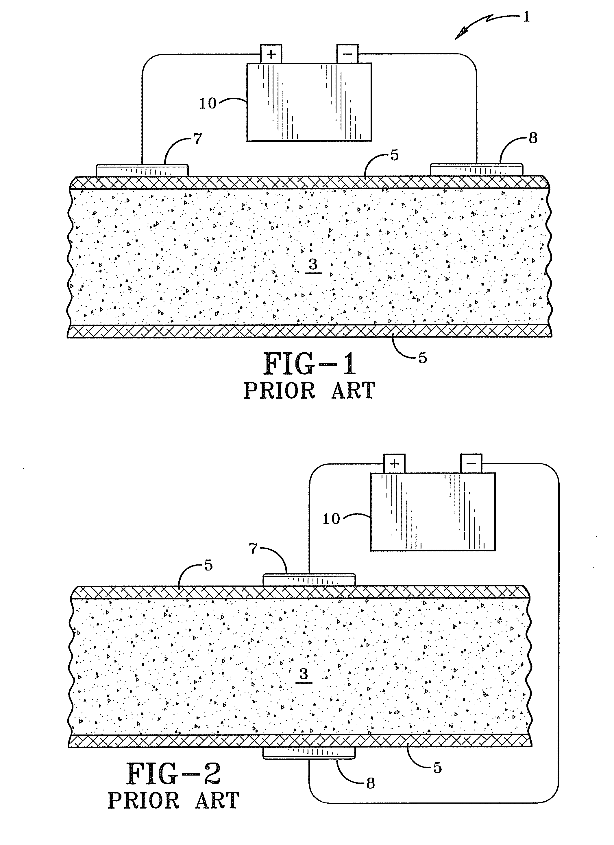
BACKGROUND OF THE INVENTION[0001]1. Technical Field[0002]The present invention relates generally to systems and methods for transdermally delivering a medical solution to a patient. More particularly, the systems and methods relate to using an ionic current for delivering the medical solution to the patient. Specifically, the methods and systems of the present invention involve an iontophoretic system and method of delivering medicine.[0003]2. Background Information[0004]An iontophoretic process of using a directed electrical current to deliver a medical solution was introduced by Giovanni Giuseppe Veratti in 1747. This process was improved upon by LeDuc in 1908. In general, as shown in FIGS. 1 and 2 an iontophoretic delivery system or method creates a small electrical current between two electrodes 7, 8 (an anode and a cathode) positioned on the skin 5 of a medical patent. The current is created by connecting each of the electrode to one terminal of a power supply 10. A medical sol...

Claims


Application Information

Patent Timeline
IPC IPC(8): A61N1/30
CPCA61N1/0432A61N1/0436A61N1/044A61N1/325A61N1/303A61N1/306A61N1/0448
Inventor RIVLIN, ALEX SAVELIJ
Owner KOPMAN STANLEY E
Learn More