Storage system

a storage system and storage technology, applied in the field of storage systems, can solve problems such as impaired reliability of storage systems, and achieve the effect of improving the reliability of storage systems

Inactive Publication Date: 2011-10-27
HITACHI LTD
View PDF9 Cites 25 Cited by
  • Summary
  • Abstract
  • Description
  • Claims
  • Application Information

AI Technical Summary

Benefits of technology

[0013]According to this invention, the reliability of storage systems can be improved even when the repetition of power saving control for power saving of storages occurs frequently due to the access from the host computer.

Problems solved by technology

In that case, the start / stop cycle count of the HDD will increase and exceed the upper limit value of the start / stop cycle count in less than three to five years that is the general hard disk life of HDDs, and the reliability of storage systems may become impaired.

Method used


Image

  • Storage system
  • Storage system
  • Storage system

Examples


second embodiment

[0125]Another embodiment in which the cycle counts are deconcentrated in an RG configured of SATA HDDs is described below. This embodiment describes changing the transition destination of the operation mode depending on the frequency by which the access interval to the RG exceeds the power saving latency.

[0126]Next, the operation of this embodiment is described below, with reference to the flowcharts in FIGS. 11 and 12.

[0127]In standing by for access from the host computer 80, the CPU 21 searches the RG status management table T3 periodically, and checks whether the RG operation mode of the field 409 is the “normal operation mode,” and at the same time, whether there are any RGs that have exceeded the power saving latency set in the selection area 708 since the last access time of the field 407 (S301). If there are such RGs, the CPU 21 refers to the RG configuration management table T2, and specifies the HDDs that configure the RGs (S302).

[0128]Next, the CPU 21 determines whether th...

third embodiment

[0141]Next, another embodiment in which an RG is configured of SAS HDDs that have the upper limit value of the start / stop cycle count is described. This embodiment describes selecting the operation mode, whether the idle operation mode or the standby operation mode, depending on the frequency by which the access interval to the RG exceeds the power saving latency.

[0142]The operation of this embodiment is described below, with reference to the flowchart in FIG. 13.

[0143]In standing by for access from the host computer 80, the CPU 21 searches the RG status management table T3 periodically, and checks whether there are such RGs that the RG operation mode of the field 409 is the “normal operation mode” and that have exceeded the power saving latency set in the selection area 708 since the last access time of the field 407 (S401). If there are such RGs, the CPU 21 refers to the RG configuration management table T2, and specifies the HDDs that configure the RGs (S402).

[0144]Next, the CPU ...

fourth embodiment

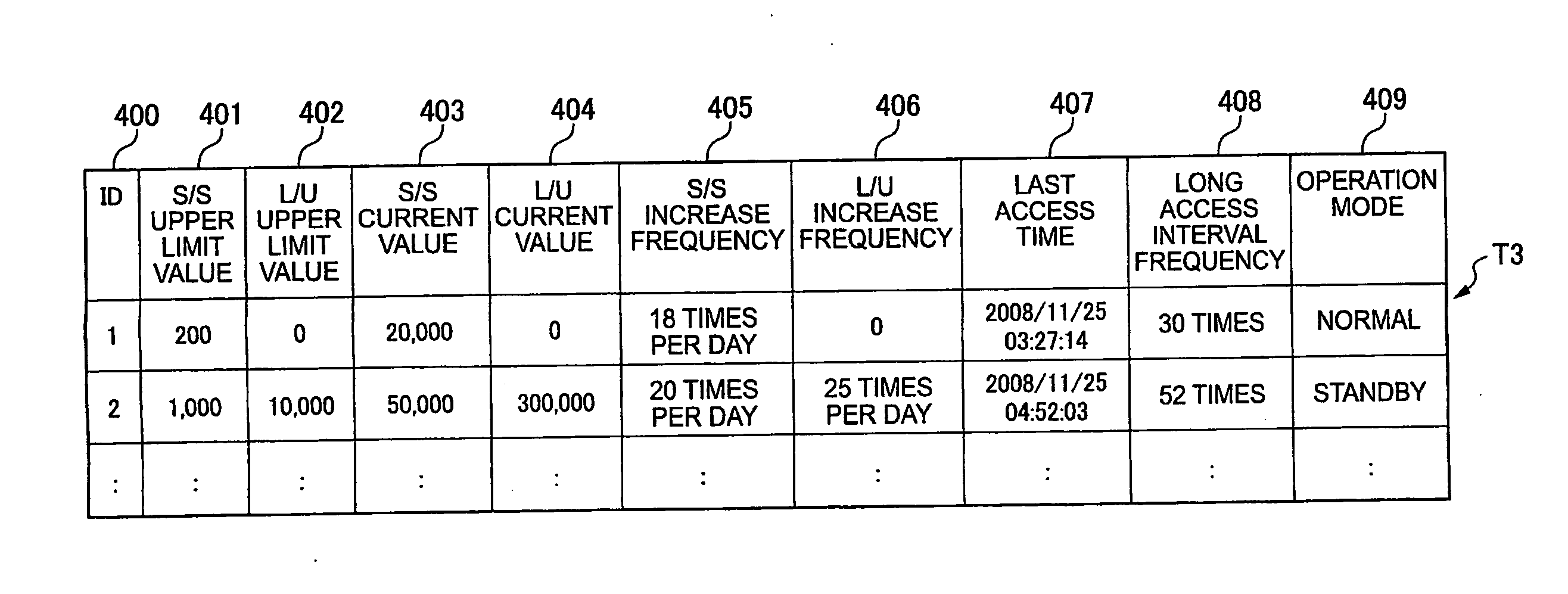
[0158]Next, the method of estimating the life of HDDs that configure an RG is described. In this embodiment, the life is estimated by calculating the date of reaching the upper limit value based on the upper limit value of the RG start / stop cycle count, the upper limit value of the RG load / unload cycle count, the current value of the RG start / stop cycle count, the current value of the RG load / unload cycle count, the increase frequency of the RG start / stop cycle count and the increase frequency of the RG load / unload cycle count, which are managed on the RG status management table T3.

[0159]Next, the method of estimating the life of HDDs that configure an RG is described with reference to the flowchart in FIG. 15. The processing in this embodiment is executed daily, before the increase frequency of the RG start / stop cycle count and the increase frequency of the RG load / unload cycle count are reset to 0.

[0160]Firstly, as for an RG with the RG ID=1, the CPU 21 compares the wear-out rate ...


PUM


Abstract

To maintain reliability even when the repetition of the power saving control for storage systems occurs frequently due to the access from the host computer. During the course of controlling the operation mode of the drives, the controller measures the start / stop cycle count and the load / unload cycle count, calculates the S / S wear-out rate showing the ratio of the measured value of the start / stop cycle count to the first upper limit value and the L / U wear-out rate showing the ratio of the measured value of the load / unload cycle count to the second upper limit value, and for the drives in the idle operation mode, selects the low-speed rotation operation mode if the S / S wear-out rate is greater than the L / U wear-out rate, or selects the standby operation mode if the S / S wear-out rate is less than the L / U wear-out rate.

Description

TECHNICAL FIELD[0001]This invention generally relates to a storage system equipped with a plurality of storage devices, and particularly to a storage system with greater reliability in the power saving control of storages.BACKGROUND ART[0002]Recently, in accordance with the increase in the amount of data, electric power consumption of data centers has dramatically increased, and power saving is required not only in servers which are primary IT (information technology) devices, it is also required in storage systems.[0003]One of the power saving technologies of a storage system equipped with hard disk drives (hereinafter referred to as HDDs) is MAID (Massive Array of Inactive Disks). MAID is the technology where power saving is realized by spinning down or powering off an HDD or a plurality of HDDs which are not accessed. In this case, if the plurality of HDDs are divided into RAID (Redundant Array of Inexpensive Disks) groups, it is common to spin down or power off the HDDs that bel...

Claims


Application Information

Patent Timeline
Patent Type & Authority Applications(United States)
IPC IPC(8): G06F12/06G06F12/00
CPCG06F1/3268G06F3/0616G06F3/0625G06F3/0634Y02B60/165G06F3/0689G06F11/3423G06F11/3485Y02B60/1246G06F3/0653Y02D10/00
Inventor OUCHI, KATSUMI
Owner HITACHI LTD
Why Eureka
Try Eureka