Storage system having network channels connecting shared cache memories to disk drives

a storage system and shared cache technology, applied in memory address/allocation/relocation, program control, instruments, etc., can solve the problems of additional translation time, impracticality of faster operation, and limit the speed of storage system operation, so as to improve the reliability of storage system, improve response speed, and reduce the cost of storage system

Inactive Publication Date: 2007-07-24
HITACHI LTD
View PDF11 Cites 16 Cited by
  • Summary
  • Abstract
  • Description
  • Claims
  • Application Information

AI Technical Summary

Benefits of technology

[0011]It is an object of the present invention to provide a storage system which is arranged to suppress bloat of the cache memory if lots of host computers are connected with the cache memory as speeding up the operation as viewed from the host computer and further to facilitate duplicate of the cache memory for the purpose of improving the reliability.
[0025]The present invention is effective in improving a response speed to the host computer by using the first cache memories, reducing the cost of the storage system by sharing the second cache memories with a plurality of host computers, and improving the reliability of the storage system by duplicating the data of the cache memory with the second cache memories.

Problems solved by technology

This thus requires a passage time of the data through the sharing network in transferring the data with the cache memory as viewed from the host computer, which leads to a limitation of speeding up the operation of the storage system.
This requires an additional translation time and makes the faster operation impractical.
This needs a great deal of cache memories.
If, therefore, lots of host computers are tried to be connected with the cache memory, the capacity of the upper cache memory is required to be gigantic.
This leads to difficulty in reducing the cost and improving the performance.

Method used


Image

  • Storage system having network channels connecting shared cache memories to disk drives
  • Storage system having network channels connecting shared cache memories to disk drives
  • Storage system having network channels connecting shared cache memories to disk drives

Examples


first embodiment

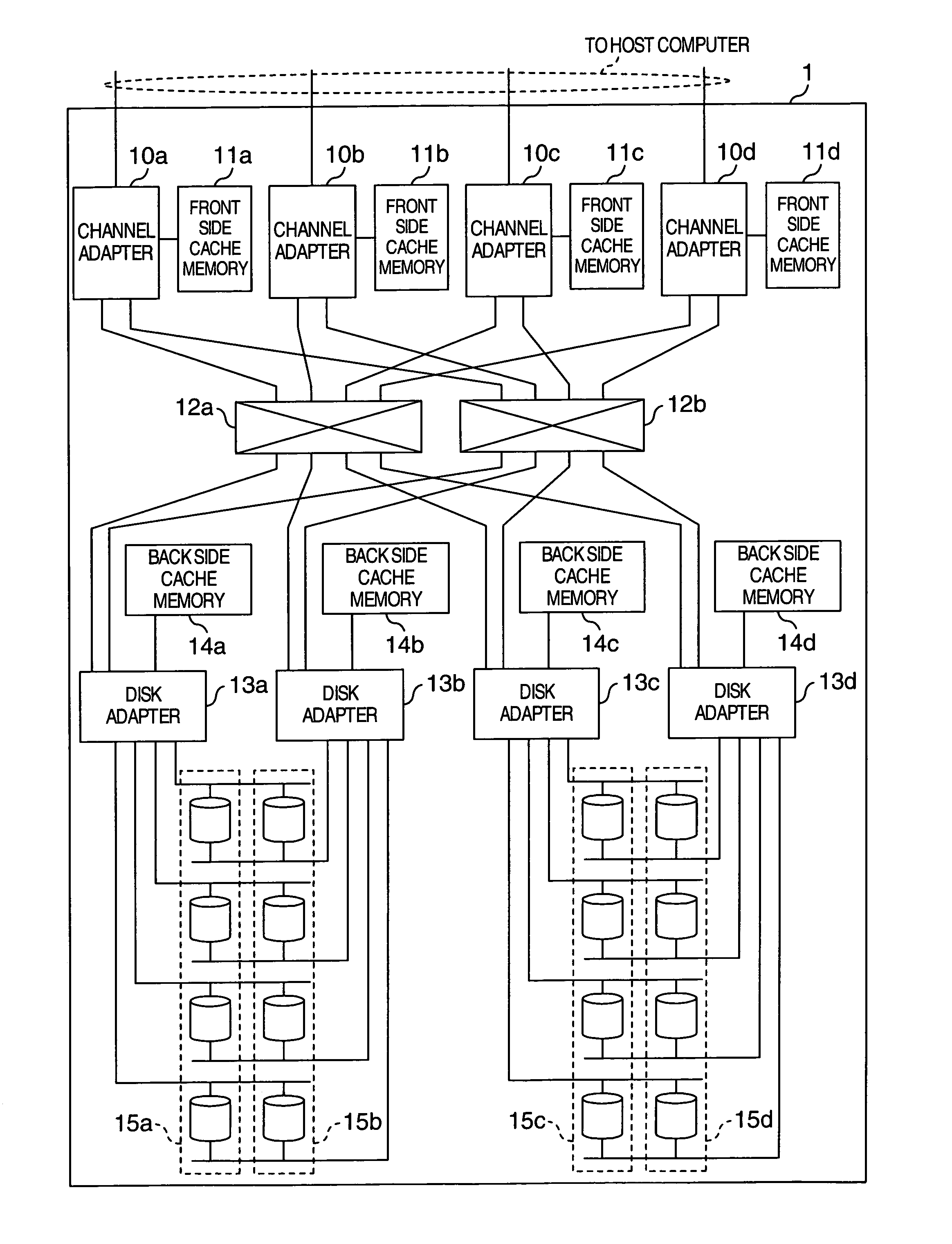
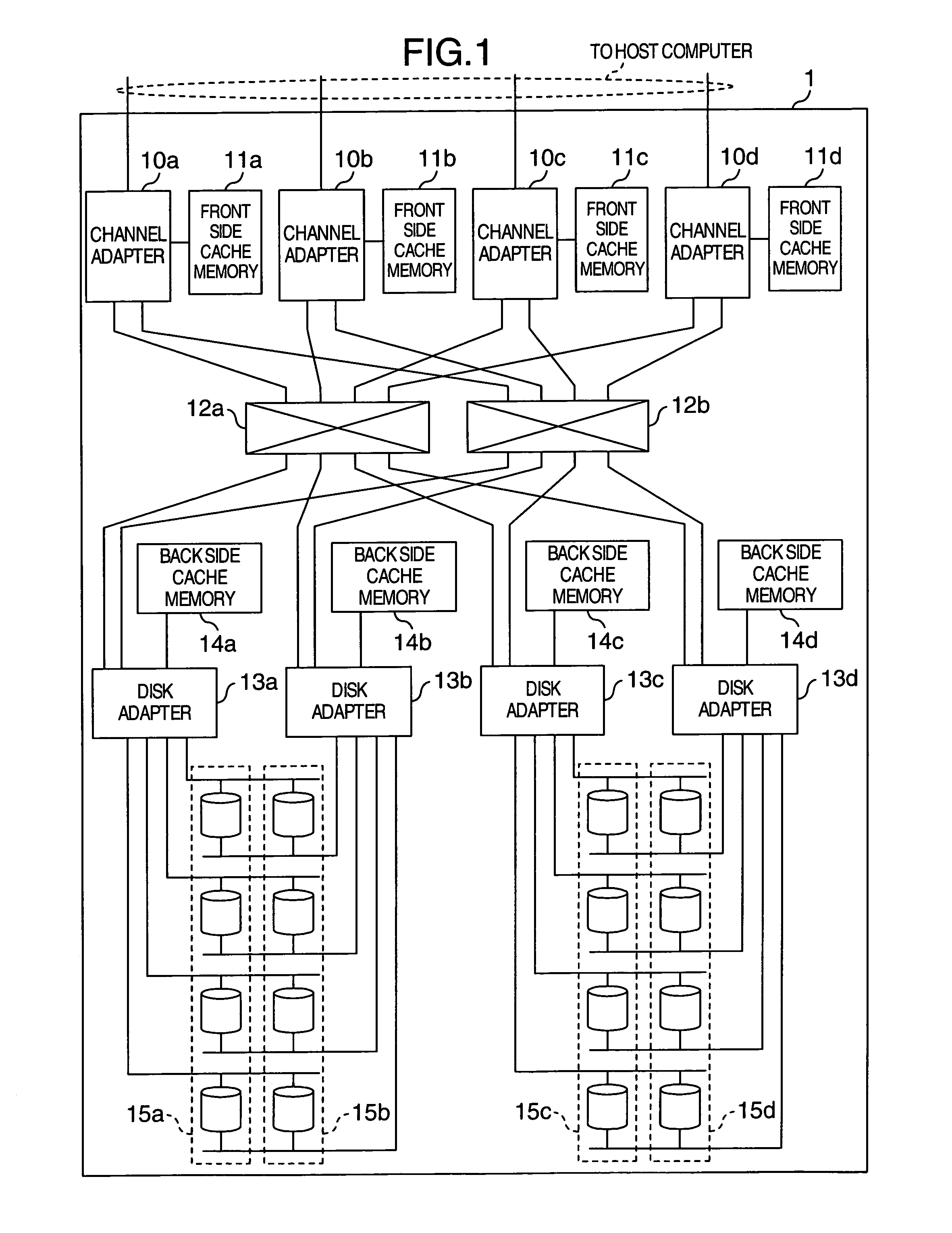
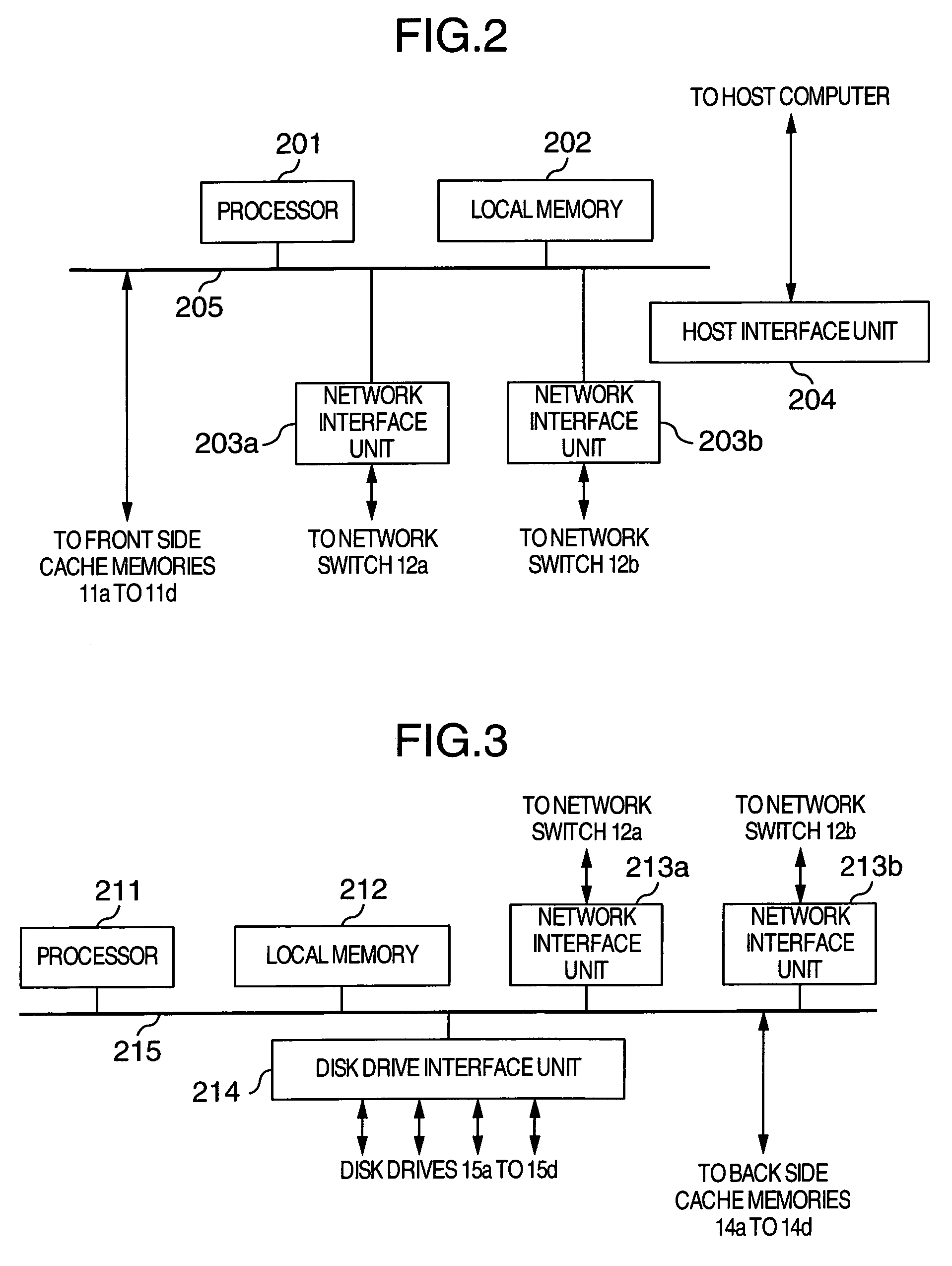
[0063]FIG. 1 is a block diagram showing an overall arrangement of the storage system according to the first embodiment of the present invention. In FIG. 1, a numeral 1 denotes a storage system, which includes channel adapters 10a to 10d for controlling connection with a host computer, disk drives 15a to 15d, disk adapters 13a-13d being connected with the disk drives 15a to 15d and for controlling read or write of data from or to the disk drives, and network switches 12a and 12b for connecting the channel adapters 10a to 10d with the disk adapters 13a to 13d. Further, the storage system 1 is equipped with front side cache memories 11a to 11d and back side cache memories 14a to 14d, the front side cache memories 11a to 11d being served as the first kind of cache memories and respectively connected with the channel adapters 10a to 10d, and the back side cache memories 14a to 14d being served as the second kind of cache memory and respectively connected with the disk adapters 13a to 13d...

second embodiment

[0095]FIG. 13 is a block diagram showing an overall arrangement of the storage system according to the second embodiment of the present invention. Like the arrangement shown in FIG. 1, in FIG. 13, the storage system 1 includes channel adapters 10a to 10d being connected with a host computer and for controlling the connecting operation, disk drives 15a to 15d, disk adapters 13a to 13d being connected with the disk drives 15a to 15d and for controlling the read and write of data from and to the disk drives, and network switches 21a and 21b being connected with the channel adapters 10a to 10d and the disk adapters 13a to 13d. Further, the storage system 1 includes the front side cache memories 11a to 11d served as the first kind of cache memory in the channel adapters 10a to 10d, respectively.

[0096]Unlike the first embodiment shown in FIG. 1, the second embodiment of the present invention is arranged so that the back side cache memories 14a to 14d served as the second kind of cache mem...

third embodiment

[0099]FIG. 14 is a block diagram showing an overall arrangement of the storage system according to the third embodiment of the present invention. In FIG. 14, the storage system 1 includes front-end (FE) adapters 20a to 20d being connected with a host computer, disk drives 15a to 15d, back-end (BE) adapters 23a to 23d being connected with the disk drives 15a to 15d, and network switches 22a and 22b for connecting the front-end adapters 20a to 20d and the back-end adapters 23a to 23d. The storage system 1 further includes front side cache memories 11a to 11d served as the first kind of cache memory in the front-end adapters 20a to 20d respectively. Moreover, the storage system 1 includes the back side cache memories 14a to 14d served as the second kind of cache memory, which are connected with the network switches 22a and 22b.

[0100]The third embodiment of the present invention is characterized by providing unified control units 24a to 24d for controlling the overall storage system. T...


PUM


Abstract

A storage system is arranged to speed up the operation and easily duplicate data without the capacity of the cache memory being so large even if lots of host computers are connected with the storage system. This storage system includes channel adapters, disk drives, disk adapters, and network switches. Further, the front side cache memories connected with the channel adapters and the back side cache memories connected with the disk adapters are provided as two layered cache system. When a request for writing data is given to the storage system by the host computer, the data is written in both the front side cache memory and the back side cache memory. The write data is duplicated by placing the write data in one of the front side cache memories and one of the back side cache memories or two of the back side cache memories.

Description

INCORPORATION BY REFERENCE[0001]The present application claims priority from Japanese patent application No. 2004-071126 filed on Mar. 12, 2004, the content of which is hereby incorporated by reference into this application.BACKGROUND OF THE INVENTION[0002]The present invention relates to storage systems equipped with disk drives, and more particularly to methods of controlling cache memory of those storage systems.[0003]Conventionally, in order to speed up an I / O operation of data to and from a host system (host computer), a storage system equipped with disk drives, in particular, a disk array system equipped with a plurality of disk drives includes a cache memory composed of far faster semiconductor memories than the disk drives themselves. Through the use of the cache memory, the storage system has operated to temporarily store data to be read from or written in the host computer. For example, this type of technology is disclosed in JP-A-11-203201.[0004]In such a technology as di...

Claims


Application Information

Patent Timeline
Patent Type & Authority Patents(United States)
IPC IPC(8): G06F12/08G06F3/06G06F12/00G06F12/16G06F13/10
CPCG06F12/0866
Inventor SHIMADA, KENTARO
Owner HITACHI LTD
Why Eureka
Try Eureka