
Valve Providing Resistant Seal and Air Expulsion in a Receptacle

Inactive Publication Date: 2011-11-03
CCL LABEL INC
View PDF5 Cites 3 Cited by
  • Summary
  • Abstract
  • Description
  • Claims
  • Application Information

AI Technical Summary

Benefits of technology

[0013]In accordance with a further embodiment of the present invention, a permeable layer of material is provided over the under layer of adhesive covering an opening in the adhesive layer. This additional layer would allow particulates to remain inside the interior of the receptacle while keeping liquids and unwanted contaminants on the exterior of the container from entering the interior of the receptacle.
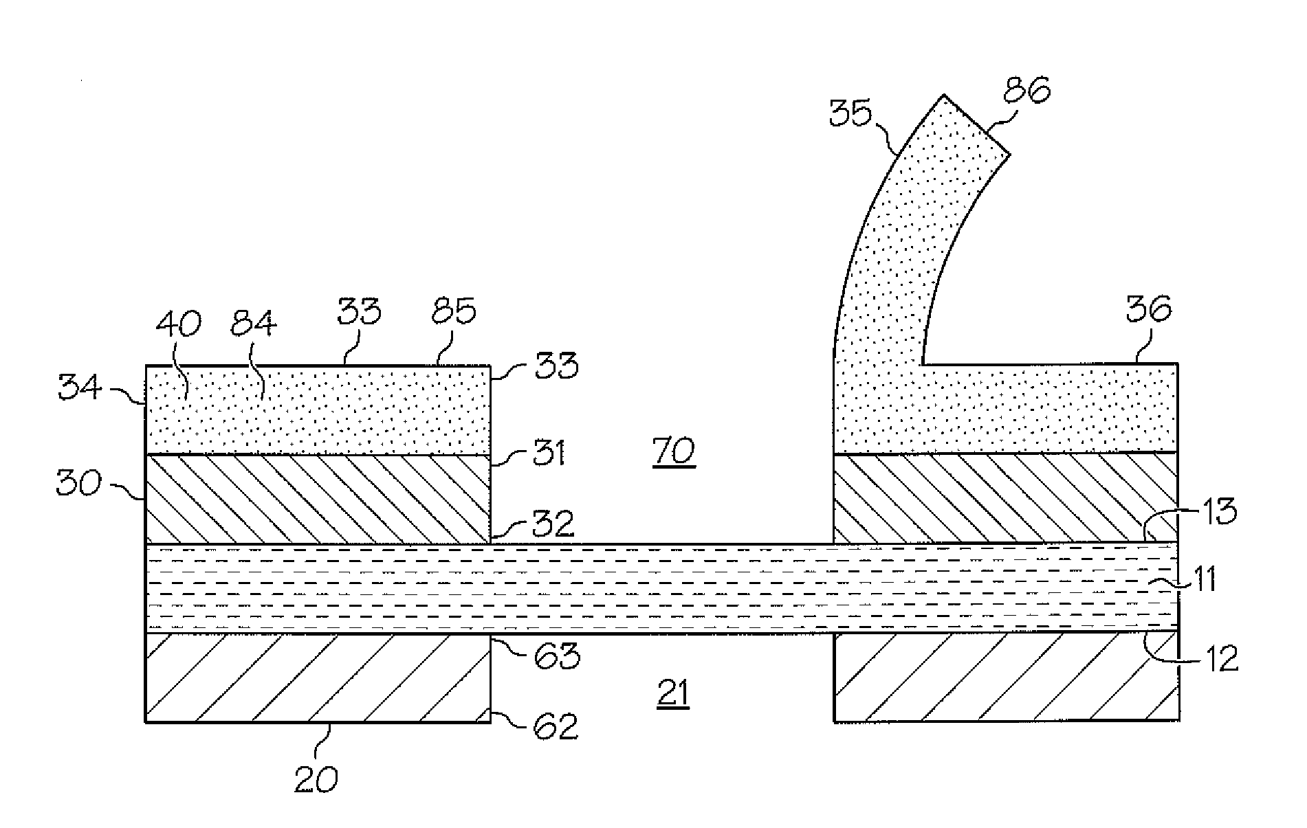
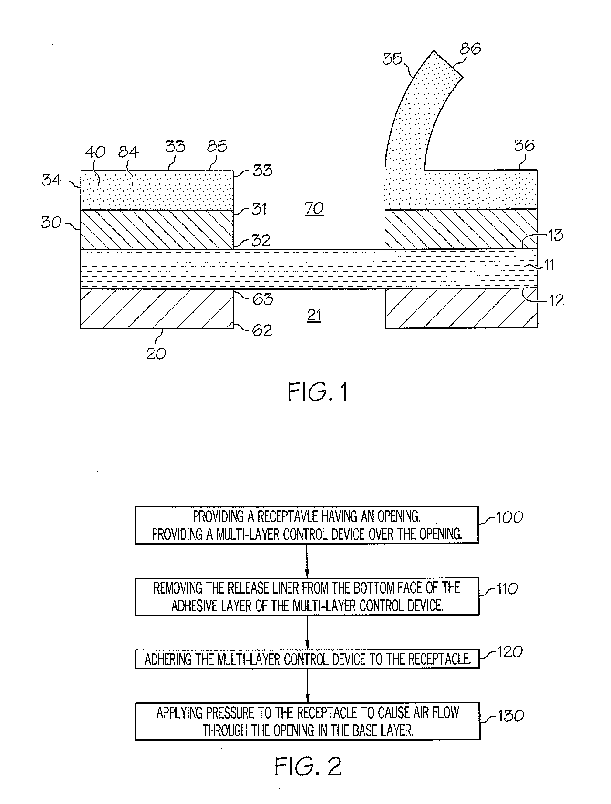
[0014]In accordance with another embodiment of the present invention, a possible method for attaching a multi-layer control device to a receptacle and releasing air pressure from the receptacle is provided. By applying pressure to the receptacle, air flows through the opening in the base layer and then navigates its way out of the perforations in the baffle layer portion. The resealable section of the baffle layer unhinges from the base layer and separates from the remainder section of the baffle layer in order to facilitate the flow of air out of the interior of the receptacle.
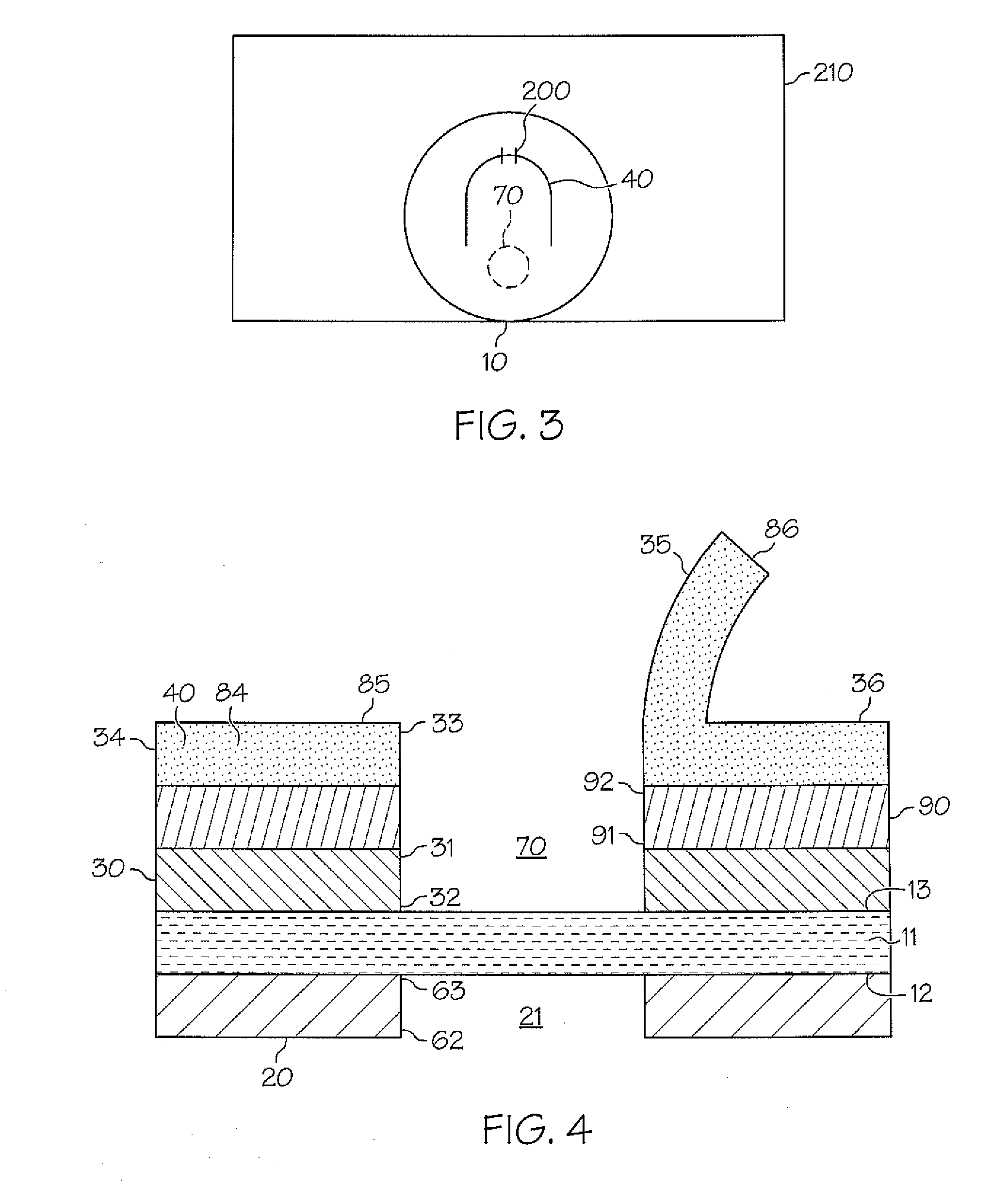
[0016]In accordance with another embodiment a multi-layer control device having a continuous top layer and a layer of flexible material capable underneath the cover layer is provided. The flexible material facilitates the expulsion of air from the interior of the receptacle.

Problems solved by technology

In accordance with one embodiment, a one-way valve is disclosed which allows for air expulsion from a receptacle but does not allow water or moisture into the interior of a receptacle.
The flow of unwanted components through the perforated baffle layer creates pressure that results in the separation of the resealable section of the baffle layer from the remainder of the baffle layer and the unhinging of the resealable section of the baffle layer from the base layer.

Method used


Image

  • Valve Providing Resistant Seal and Air Expulsion in a Receptacle
  • Valve Providing Resistant Seal and Air Expulsion in a Receptacle
  • Valve Providing Resistant Seal and Air Expulsion in a Receptacle

Examples


Embodiment Construction

[0024]The present invention is now illustrated in greater detail by way of the following detailed description which represents the best presently known mode of carrying out the invention. However, it should be understood that this description is not to be used to limit the present invention, but rather, is provided for the purpose of illustrating the general features of the invention.

[0025]Referring now to the Figures and initially to FIG. 1, a multi-layer control device 10 that provides an effective seal while still enabling the expulsion of unwanted components 60 from a receptacle to which the device 10 is attached, is disclosed. The multi-layer control device 10 includes a patterned under layer of adhesive 20 forming an opening 21. The adhesive has a top face 63 and a bottom face 62. A permeable layer 11 may be included and has a top face 13 and a bottom face 12 provided over the top face 63 of the adhesive layer 20. The permeable layer 11 covers the opening and the patterned und...


PUM


Abstract

A multi-layer control device comprising an adhesive layer, a base layer provided over the underlayer of adhesive, a baffle layer having a resealable section and a remainder section. The resealable section is able to detach from the remainder section of the baffle layer. The base layer has an opening to allow the expulsion of air within a receptacle while maintaining a seal from the outside environment. The interaction between the base layer and the baffle layer generates static energy. A method for adhering a multi-layer control device to a receptacle and releasing air pressure is also provided.

Description

CROSS-REFERENCE TO RELATED APPLICATION[0001]The present application claims the benefit of U.S. Provisional Application No. 61 / 310,740 filed Mar. 5, 2010, which is incorporated herein by reference in its entirety.FIELD OF THE INVENTION[0002]The present invention relates to valves. More specifically, the present invention relates to valves that provide a hermetic or water resistant seal but allow for the release of air pressure.BACKGROUND OF THE INVENTION[0003]A common problem with consumer or industrial packaging is excess air inside the receptacle. Often, it is desirable for a receptacle to provide a dry environment as well as to allow for air expulsion during package distribution, so that packages can be shipped flat and more packages can be fit within the trailer or rail car. In order to provide such an environment for a product, receptacles often times have small perforations, and must be kept in a dry environment in order to avoid water and moisture from entering the receptacle ...

Claims


Application Information

Patent Timeline
IPC IPC(8): F16K21/04B32B7/04B32B3/08
CPCB65D77/225Y10T428/24322Y10T428/14Y10T137/7837
Inventor SELINE, DAVID W.RUSIN, MARY BETH
Owner CCL LABEL INC
Learn More