Barrier catheter apparatus and method

a catheter and catheter technology, applied in the field of catheter improvement, can solve the problems of catheter obstruction, catheter obstruction, and catheter obstruction, and achieve the effect of avoiding catheter obstruction and avoiding catheter obstruction

Active Publication Date: 2011-01-25
MEDTRONIC MIMIMED INC
View PDF12 Cites 3 Cited by
  • Summary
  • Abstract
  • Description
  • Claims
  • Application Information

AI Technical Summary

Benefits of technology

[0012]Therefore, it is an advantage of embodiments of the present invention to provide a catheter which provides a significant barrier to diffusion of CO2 and other substances into the lumen of the catheter.
[0013]It is a further advantage of embodiments of the present invention to provide a catheter that inhibits diffusion of preservatives and other substances within an infusion formulation outward through the walls of the catheter and into the body of the patient before reaching the distal end of the catheter.
[0014]It is a further advantage of embodiments of the present invention to provide a catheter which inhibits deposit formation that can tend to occur at or near the distal end tip and facilitates the expulsion during delivery, for example, delivery of a bolus or catheter flush.
[0016]In a preferred embodiment of the present invention, a barrier layer is provided within the catheter that is comprised of material which has a lower permeability than conventional materials used in the wall of a catheter. Thus, preferably, the barrier layer material has a lower permeability for molecules in the infusion formulation and in the environment of use than conventional materials used in the wall of a catheter. Thus, the properties, composition, and / or stability of the infusion formulation delivered to the infusion site may be more accurately controlled. In one preferred embodiment, the undesirable substance is believed to be CO2 and the infusion formulation comprises an insulin formulation.
[0017]Preferred embodiments of the present invention also provide a catheter which inhibits deposit formation at the distal end tip and facilitates the expulsion during delivery of a bolus or catheter flush. According to one embodiment, a flared distal end tip aids in the release, during a bolus delivery or catheter flush, of any obstruction situated at the distal end tip of the catheter. The larger cross-sectional area of the inner channel of the lumen at the flared distal end tip minimizes the chances that any obstruction that develops at or near the distal end tip will be sufficient to hinder the flow of the infusion formulation within the lumen of the catheter. In addition, deposits that do form in the flared portion of the distal end tip are more likely to be expelled during a bolus delivery or catheter flush due to the shape and larger cross-sectional area of the flare.
[0018]Further preferred embodiments of the present invention also provide a catheter which inhibits deposit formation at or near the distal end tip by providing a slit valve that greatly reduces the potential for obstructions resulting from the mixing of body fluids with the infusion formulation during the interval between pump strokes of an infusion pump. The slit valve comprises a portion of the outer layer material extended over the distal end with one or more and, preferably a plurality of slits that may be elastically extended to an open position by the expulsion of the infusion formulation during a pump stroke of the infusion pump. During the interval between pump strokes, the slits will return to a closed position and hinder the inflow of body fluid into the distal end tip.

Problems solved by technology

The diffusion of certain molecules may lead to the formation of catheter obstructions.
For example, it is believed that diffusion of one or more molecules (for example, of CO2 and / or phenol) through the wall of a catheter carrying an insulin formulation may lead to precipitation and eventually to the formation of deposits that may result in catheter obstructions.
In addition, obstructions often form at the distal end tip of the catheter, possibly as a result of CO2 mixing with the infusion formulation that is present near the tip, especially during the interval between pump strokes of the IIP.
An additional problem with inward diffusion of molecules through the wall of a catheter is that the molecules interact with the infusion formulation.
Thus, the composition of the infusion formulation within the catheter may be destabilized.
This makes it difficult to accurately control the properties, composition, and / or stability of the infusion formulation delivered to the infusion site.
Along with the problem of diffusion of molecules through the wall into the catheter is the related problem of outward diffusion of molecules of the infusion formulation components through the wall of the catheter and into the patient at other than the infusion site.
Again, as a result of this outward diffusion, the properties, composition, and / or stability of the infusion formulation delivered to the infusion site will be difficult to control.
Furthermore, it is believed that the diffusion of phenol from the insulin formulation destabilizes the insulin formulation and has a tendency to precipitate and lead to the formation of catheter obstructions.
Both of these materials can be insufficient barriers to diffusion.
CO2 and other substances present in body fluids may diffuse and / or mix with the infusion formulation in the distal end tip and cause obstructions to form.

Method used


Image

  • Barrier catheter apparatus and method
  • Barrier catheter apparatus and method
  • Barrier catheter apparatus and method

Examples


Embodiment Construction

[0030]In the following description of preferred embodiments, reference is made to the accompanying drawings which form a part hereof, and in which is shown by way of illustration specific embodiments in which the invention may be practiced. It is to be understood that other embodiments may be utilized and structural changes may be made without departing from the scope of the preferred embodiments of the present invention.

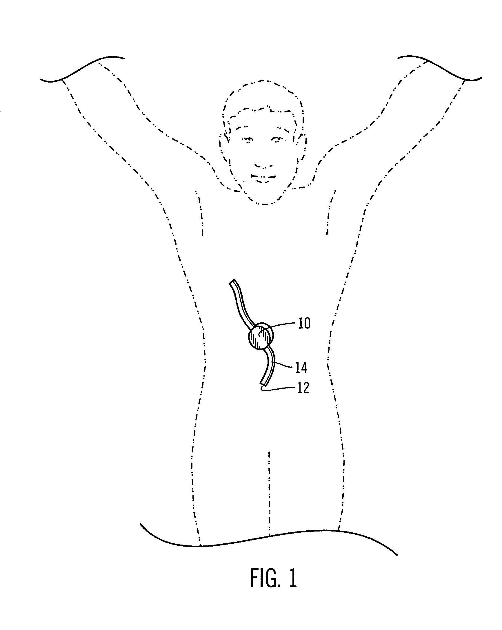
[0031]As discussed above, the present invention relates generally to an improved catheter. Embodiments of the invention may be employed in various infusion environments including, but not limited to a biological implant environment. In preferred embodiments, a catheter is configured for an implant environment within a human body, as shown in FIG. 1. However, other embodiments may be employed in other biological implant or non-implant environments.

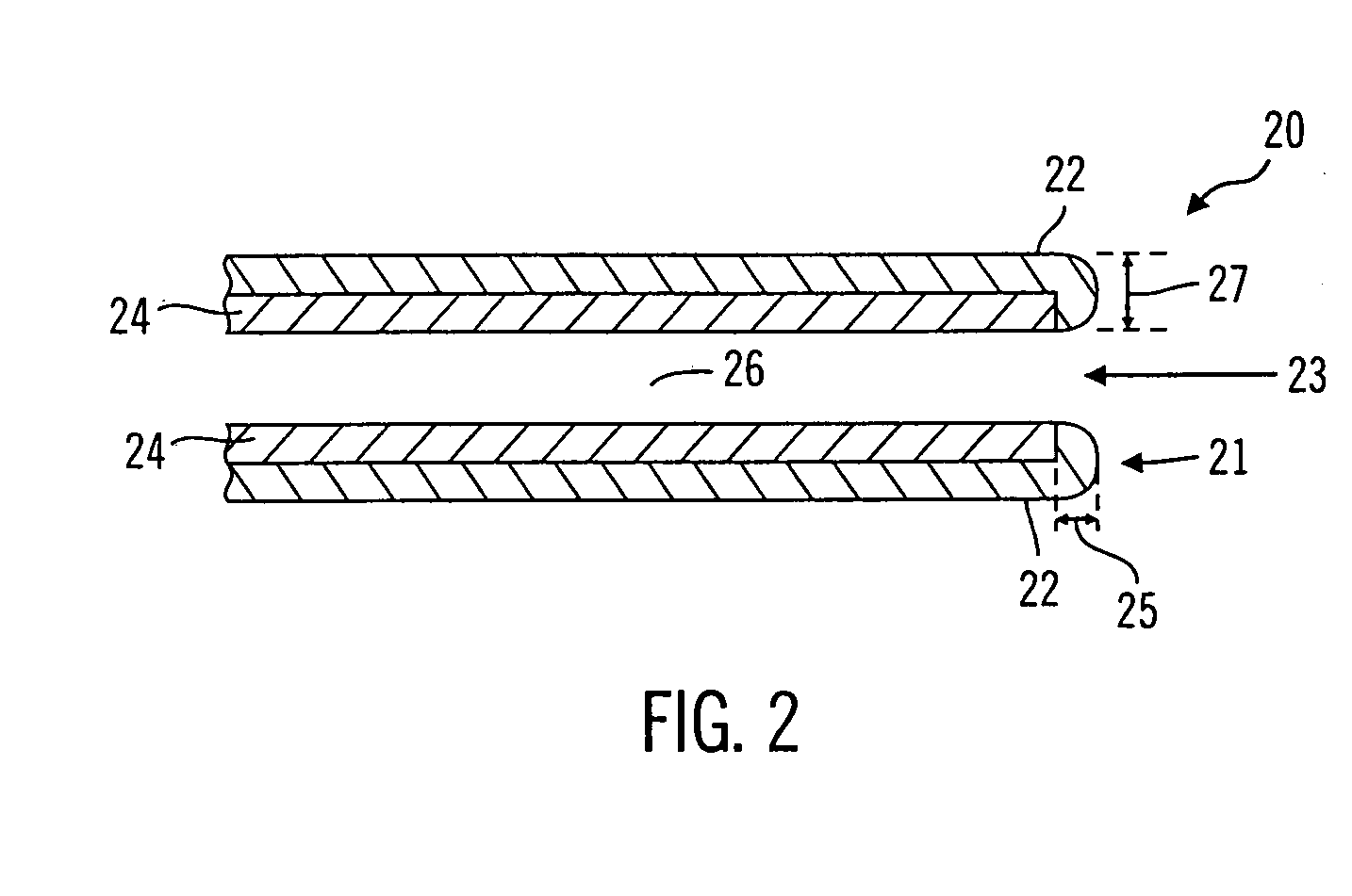
[0032]FIG. 2 illustrates an example of a catheter 20 according to one preferred embodiment of the present invention. Cath...


PUM

PropertyMeasurementUnit
distancesaaaaaaaaaa
diameteraaaaaaaaaa
distanceaaaaaaaaaa

Abstract

A catheter for use in delivery or withdrawal of a formulation, wherein the catheter has an outer layer comprising a bio-compatible material and a barrier layer comprising a material that provides a more effective barrier than the outer layer against inward and outward diffusion of substances that may cause destabilization of the formulation. The catheter may include a flared distal end tip to aid in the release, during a bolus delivery or catheter flush, of any obstruction situated at the distal end tip of the catheter. The catheter may also include a slit valve at the distal end tip which has one or more and, preferably a plurality of slits that may be elastically extended to an open position by the expulsion of the formulation during an IIP pump stroke. During the interval between IIP pump strokes, the slits return to a closed position and hinder the inflow of body fluid into the distal end tip.

Description

CROSS-REFERENCE TO RELATED APPLICATIONS[0001]This application is a divisional of application Ser. No. 10 / 036,081 filed Dec. 28, 2001, which is in turn claims the benefit of prior filed U.S. Provisional Application Ser. No. 60 / 317,358, filed Sep. 5, 2001 and relate to co-pending U.S. patent application Ser. No. 10 / 035,831, filed Dec. 28, 2001. The entirety of each which are incorporated herein by reference.BACKGROUND OF THE INVENTION[0002]1. Field of the Invention[0003]The present invention relates, generally, to improvements in catheters, and, in preferred embodiments, to a catheter that significantly reduces diffusion of substances through the catheter wall and, in further preferred embodiments, possibly hinders the formation of obstructions in the distal end tip of the catheter.[0004]2. Description of Related Art[0005]In the medical arts, catheters are used to inject fluids into or drain fluids away from the body. Catheters may be used in combination with a device such as a pump, ...

Claims


Application Information

Patent Timeline
Patent Type & Authority Patents(United States)
IPC IPC(8): A61M5/00A61M25/18A61L29/08A61L29/10A61M5/142A61M25/00
CPCA61L29/085A61L29/103A61M25/0068A61M5/14276A61M25/005A61M2025/0073A61M2025/0076
Inventor CHONG, COLINOBERG, KEITHMOUNCE, PAULLORD, PETER C.VAN ANTWERP, WILLIAM P.
Owner MEDTRONIC MIMIMED INC
Why Eureka
Try Eureka