Gas injection system for ion beam device

a technology of gas injection system and ion beam, which is applied in the direction of basic electric elements, electric discharge tubes, electrical equipment, etc., can solve the problems of inefficient and ineffective delivery of residue removal gases, and affecting the quality of finished substrates

Active Publication Date: 2018-01-09
VARIAN SEMICON EQUIP ASSOC INC
View PDF2 Cites 2 Cited by
  • Summary
  • Abstract
  • Description
  • Claims
  • Application Information

AI Technical Summary

Benefits of technology

[0008]An exemplary embodiment of a gas injection system for an ion beam device in accordance with the present disclosure may include an extraction plate having an extraction aperture for allowing passage of an ion beam through the extraction plate, the extraction plate further having a gas slot for facilitating expulsion of gas from the extraction plate.

Problems solved by technology

This residue can be detrimental to the quality of a finished substrate if not removed.
Much of the residue removal gases are removed from the process chamber before reaching the surface of the substrate, resulting in inefficient and ineffective delivery of the residue removal gases.

Method used


Image

  • Gas injection system for ion beam device
  • Gas injection system for ion beam device
  • Gas injection system for ion beam device

Examples


Embodiment Construction

[0021]The present embodiments will now be described more fully hereinafter with reference to the accompanying drawings, wherein some embodiments are shown. The subject matter of the present disclosure may be embodied in many different forms and are not to be construed as limited to the embodiments set forth herein. These embodiments are provided so this disclosure will be thorough and complete, and will fully convey the scope of the subject matter to those skilled in the art. In the drawings, like numbers refer to like elements throughout.

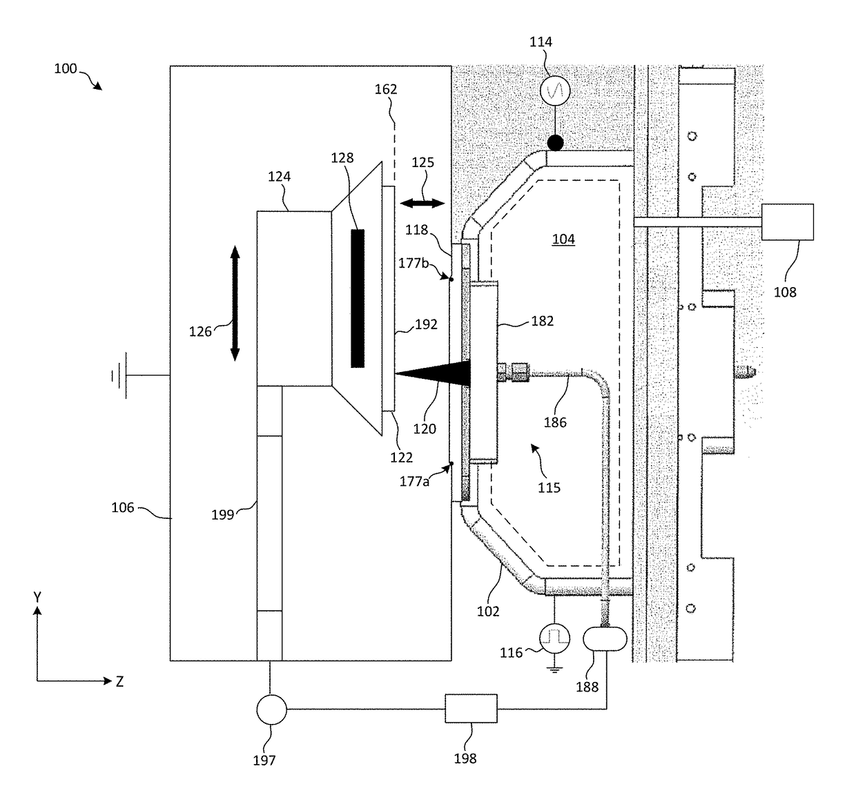
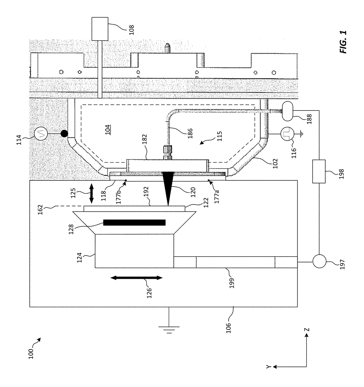
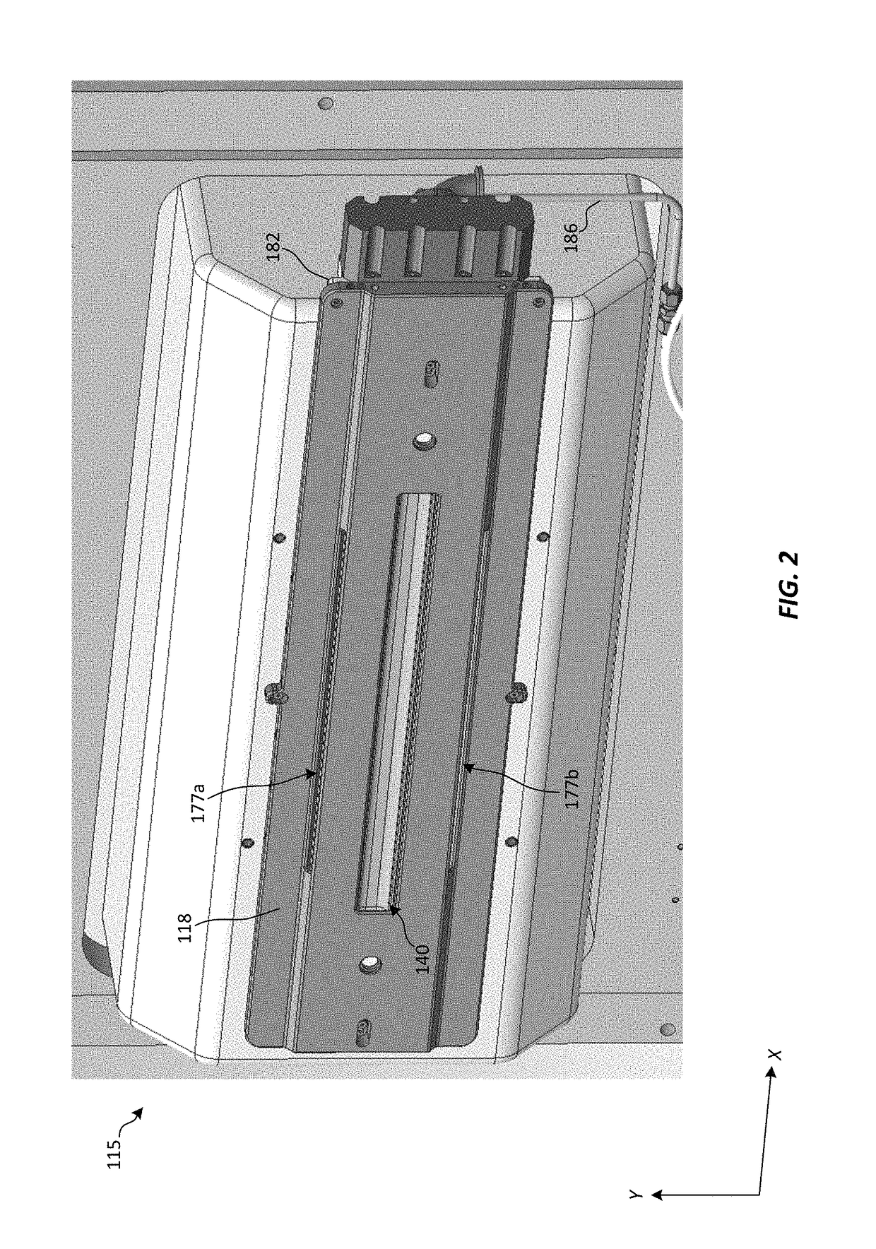
[0022]The present embodiments provide a novel system and method for treating substrates, and in particular a novel gas injection system and method of manufacturing the same, such system adapted to remove residual etched material from a substrate surface. In particular embodiments, an extraction plate having integrated gas slots for emitting one or more residue removal gases in close proximity to a substrate surface before, during, and / or after etch...


PUM


Abstract

A gas injection system, including an extraction plate having an extraction aperture for allowing passage of an ion beam through the extraction plate, the extraction plate further having a gas slot for expulsion of a residue removal gas from the extraction plate. The gas injection system may include a gas conduit extending through the extraction plate between the gas slot and a gas manifold, a gas source connected in fluid communication with the gas manifold, the gas source containing the residue removal gas. The gas manifold may include a valve adjustable between a first position, wherein the residue removal gas is allowed to flow into the extraction plate, and a second portion, wherein the residue removal gas can be vented from the extraction plate. The gas injection system may further include a manifold cover coupled to the gas manifold.

Description

RELATED APPLICATIONS[0001]This application claims priority to U.S. Provisional Patent Application No. 62 / 436,047, filed Dec. 19, 2016, entitled “GAS INJECTION SYSTEM FOR ION BEAM DEVICE,” which is incorporated by reference herein in its entirety.FIELD OF THE DISCLOSURE[0002]Embodiments of the present disclosure relate to the field of ion beam devices, and more particularly to an apparatus and method for injecting residue removal gases into a process chamber of an ion beam device.BACKGROUND OF THE DISCLOSURE[0003]In order to create desired surface features on a semiconductor wafer or other substrate, an ion beam of prescribed energy may be projected onto the surface of the substrate in a predetermined pattern to “etch” the desired features into the substrate. During this etching process, the substrate can be mechanically driven or “scanned” in a direction transverse to an ion beam projected onto the substrate by an ion source. For example, if an ion beam is projected along a horizont...

Claims


Application Information

Patent Timeline
Patent Type & Authority Patents(United States)
IPC IPC(8): H01J37/32H01J37/305
CPCH01J37/32449H01J37/3056H01J2237/31749H01J2237/3174H01J2237/006H01J37/3244H01J37/02
Inventor WALLACE, JAYALLEN, ERNEST E.HERTEL, RICHARD J.KONTOS, ALEXANDER C.LIANG, SHURONGKRAMPERT, JEFFREY E.ROCKWELL, TYLER
Owner VARIAN SEMICON EQUIP ASSOC INC
Why Eureka
Try Eureka