Storage System

a storage system and storage technology, applied in the field of storage systems, can solve the problems of limiting the type of objects that may be hung from such hooks, limiting the use of pegboard storage systems, and limiting the type of objects that can be installed on such hooks, so as to increase usability, function, and facilitate installation.

Active Publication Date: 2011-11-03
ILLINOIS TOOL WORKS INC
View PDF4 Cites 21 Cited by
  • Summary
  • Abstract
  • Description
  • Claims
  • Application Information

AI Technical Summary

Benefits of technology

[0007]What is needed is a storage system mountable to a wall that may be easily installed at any number of locations chosen by a user, whereby the storage system has increased usability, function, pullout resistance and load capacity.

Problems solved by technology

Pegboard storage systems suffer from limiting a user to install hooks or objects at predetermined locations and typically are large and take up several square feet of wall space.
In addition, hooks inserted into pegboard limit the type of objects that may be hung from such hooks.
For example, a traditional pegboard hook would not allow a user to hang a ladder, rake, bicycle or other such object with substantial height.
Slot-wall systems may be slightly cumbersome for a user, as these systems generally require at least one open side in order to insert hooks or other attachments.
These systems typically are time intensive to install as many holes need to be drilled and measured to ensure the systems are installed properly and level, and a significant number of screws are generally used to affix the systems to the wall.

Method used


Image

  • Storage System
  • Storage System
  • Storage System

Examples


Embodiment Construction

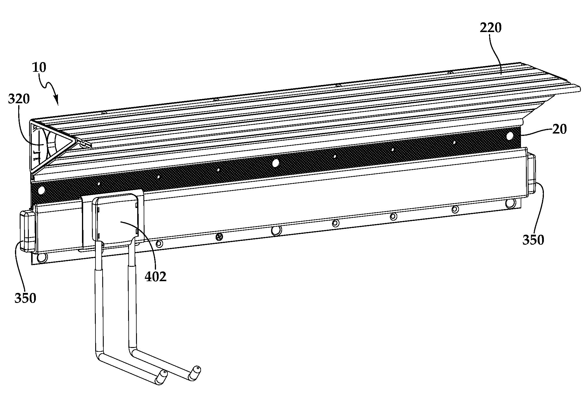
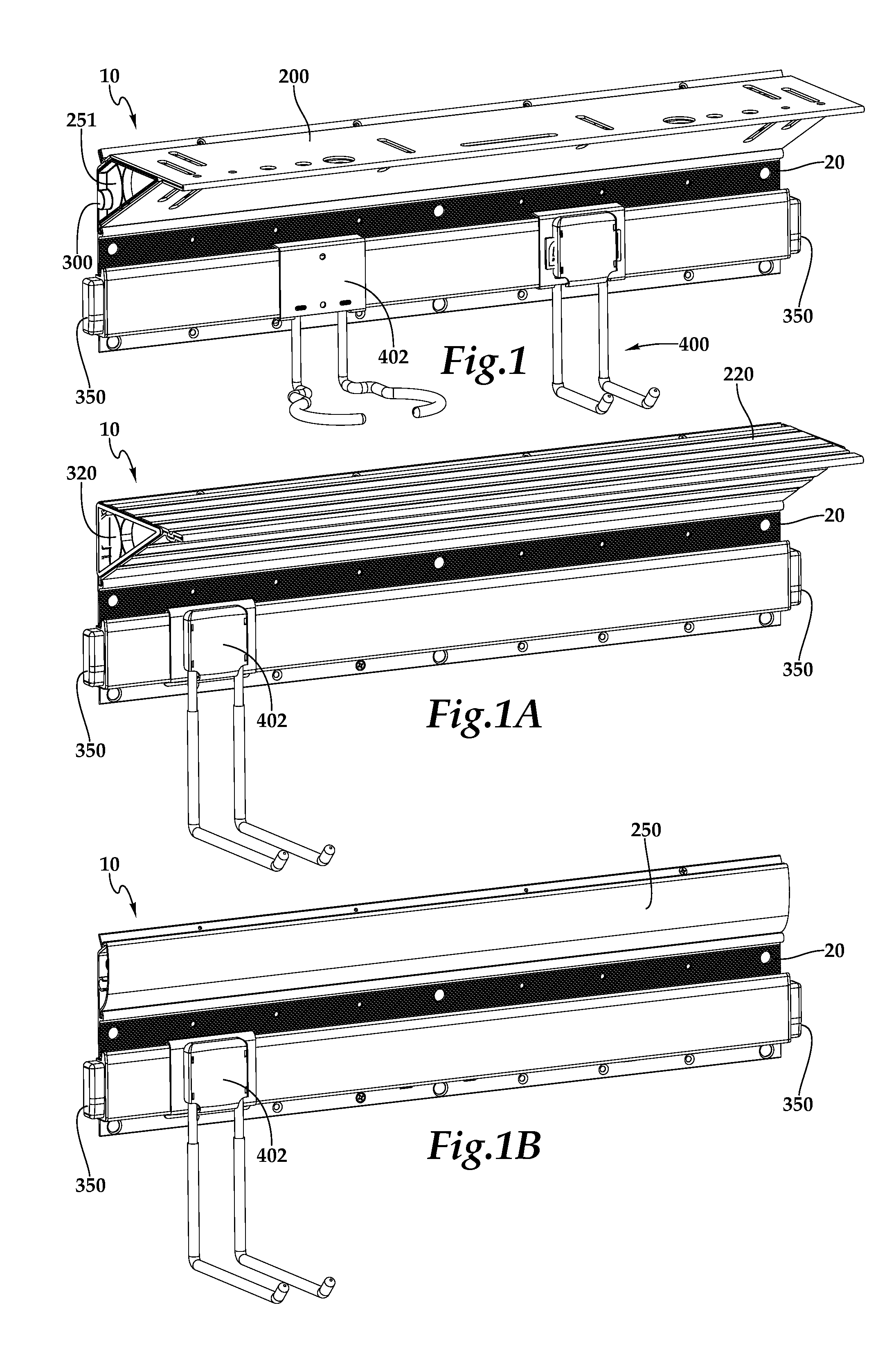
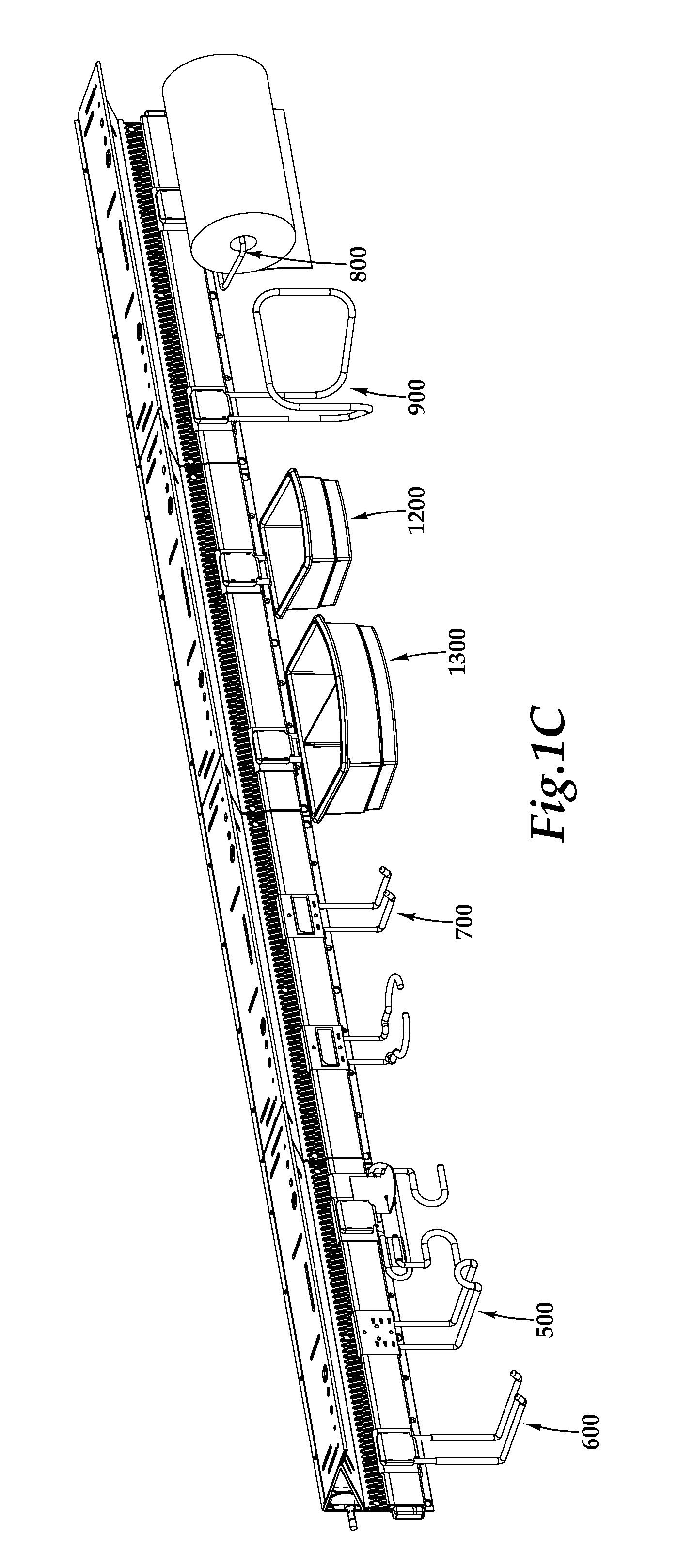
[0057]Rail storage system 10 is mountable to a wall, mounting surface or substrate such as drywall with at least one fastener and system 10 is used for holding, typically hanging, objects (not shown), such as a tool, a rake, a ladder or the like. Referring to FIGS. 1 and 2, rail storage system 10 may include base or rail 20 and at least one accessory 400. As shown in FIGS. 1 and 2, system 10 further may include a shelf 200, a cover 250, an upper endcap 300 and / or a lower endcap or connector 350. As shown in FIG. 1C, system 10 may be coupled to one or more additional systems 10.

[0058]Base

[0059]Referring to FIGS. 1-3, a storage system 10 may include a base or rail 20 having a front surface 22, a rear surface 24, a top or upper edge 26, a bottom or lower edge 28 and sides 30. Base 20 further may have a plurality of portions, such as portions 32, 40, 60, 80, 100, 110, 150 and 160. In one embodiment, as shown in FIG. 3, each portion 32, 40, 60, 80, 100, 110, 150 and 160 extends along ent...


PUM


Abstract

In one aspect, a storage system is disclosed. The storage system may include a base having a lower or accessory portion and an upper portion, wherein the lower portion has at least one lower projection extending outward from a front surface and wherein the upper portion has at least two upper projections extending outward from the front surface and spaced from the lower projection. The system may also include at least one accessory configured to engage the lower portion. The system further may include at least one shelf or cover configured to engage the two upper projections. In a further aspect, another storage system is disclosed, wherein the storage system may include a base having an upper ledge portion, wherein a portion of the upper ledge portion is spaced a predetermined distance from a wall. The base further may include a lower portion and an accessory portion between the upper ledge portion and the lower portion. The system further may include at least one accessory configured to engage the accessory portion. The system also may include at least one shelf or cover configured to couple to the base.

Description

CROSS-REFERENCE TO RELATED APPLICATIONS[0001]The present application claims benefit of priority of U.S. Provisional Application 61 / 330,808, filed on May 3, 2010, and U.S. Provisional Application 61 / 415,595, filed on Nov. 19, 2010.BACKGROUND OF THE INVENTION[0002]1. Field of the Invention[0003]The present invention is directed to a storage system, mountable on a wall for holding or organizing an object or plurality of objects such as household items.[0004]2. Description of the Related Art[0005]Wall mounted storage systems have traditionally come in pegboard or those that use variations of a slot-wall. Pegboard storage systems suffer from limiting a user to install hooks or objects at predetermined locations and typically are large and take up several square feet of wall space. In addition, hooks inserted into pegboard limit the type of objects that may be hung from such hooks. For example, a traditional pegboard hook would not allow a user to hang a ladder, rake, bicycle or other suc...

Claims


Application Information

Patent Timeline
Patent Type & Authority Applications(United States)
IPC IPC(8): B65D25/22
CPCA47B96/067B25H3/04A47F5/0838
Inventor ERNST, RICHARD J.GRIMM, JOHN P.
Owner ILLINOIS TOOL WORKS INC
Why Eureka
Try Eureka