Organic light-emitting device
a light-emitting device and organic technology, applied in the direction of thermoelectric devices, other domestic objects, luminescent compositions, etc., can solve the problems of low weight of the compound, degrading the emission efficiency of an emission layer, and difficulty in smooth transportation of holes, etc., to achieve high emission efficiency
- Summary
- Abstract
- Description
- Claims
- Application Information
AI Technical Summary
Benefits of technology
Problems solved by technology
Method used
Image

Examples
example
Example 1
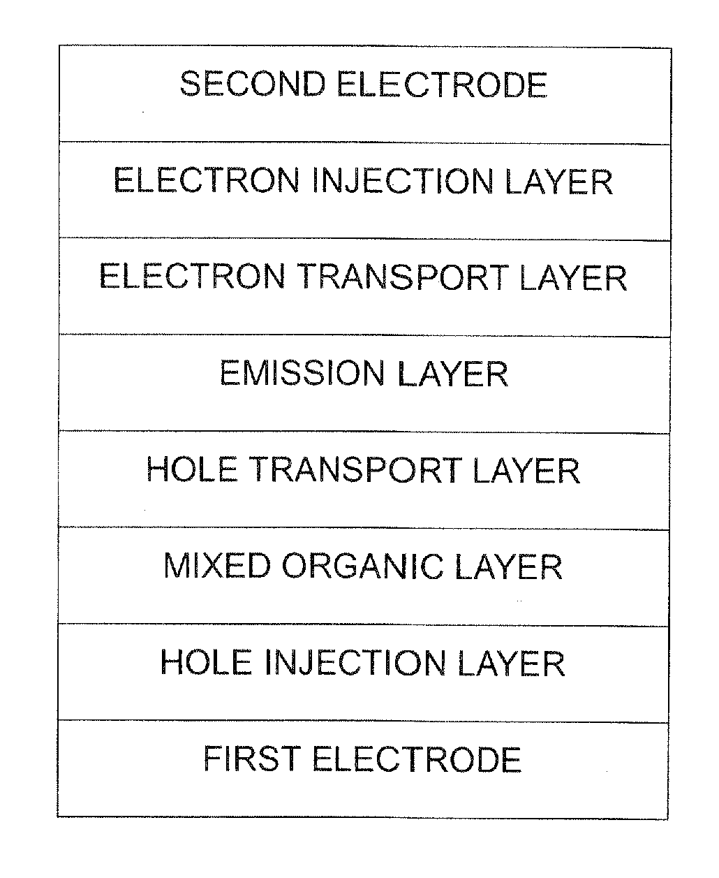
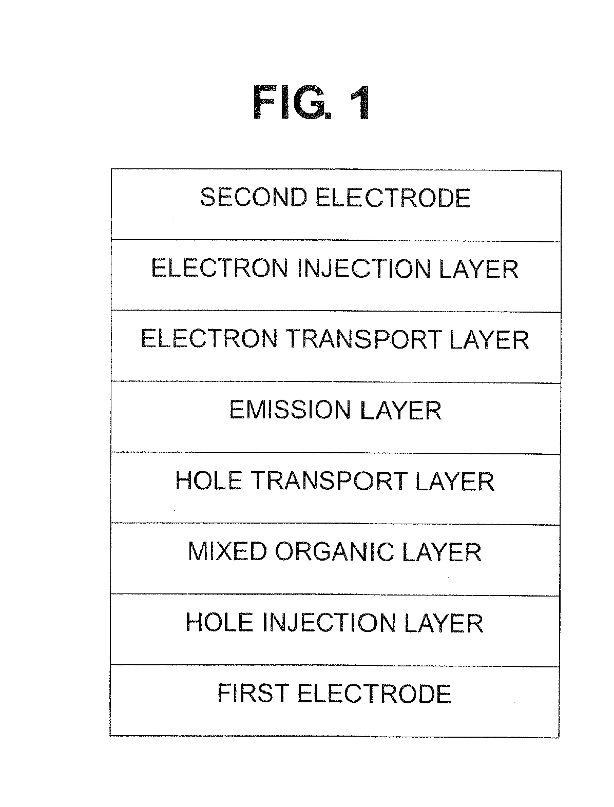
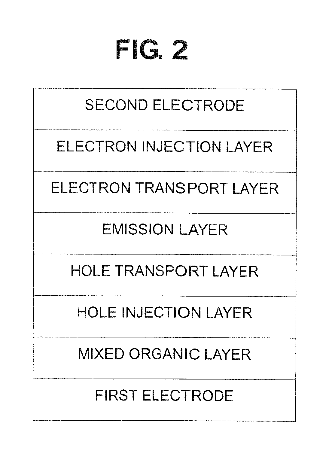
[0060]To manufacture a first electrode, a Corning 15 Ω / cm2 (1200 Å) ITO glass substrate was cut to a size of 50 mm×50 mm×0.7 mm and then sonicated in isopropyl alcohol and pure water each for five minutes, and then cleaned by irradiation of ultraviolet rays for 30 minutes and exposure to ozone. The resulting ITO glass substrate was mounted into a vacuum deposition device.
[0061]Compound 6 that is a fluorene derivative and hexaazatriphenylenehexacarboxylnitrile that is a pyrazine derivative were deposited in a weight ratio of 99:1 on the glass substrate in which the first electrode was patterned, thereby forming a mixed organic layer having a thickness of 50 nm.
[0062]4,4′-bis(3-methyl-9-carbazolyl)-1,1′-biphenyl was deposited on the mixed organic layer, thereby forming a hole transport layer having a thickness of 100 nm.
[0063]A host Compound 13 and a dopant Compound 17 were co-deposited in the weight ratio of 97:3 on the hole transport layer, thereby forming an emission layer...
example 2
[0065]An organic light-emitting device was manufactured in the same manner as in Example 1, except that a mixed organic layer having a thickness of 50 nm was formed by co-depositing hexaazatriphenylene hexacarboxylnitrile and Compound 1, which is a fluorene derivative, in a weight ratio of 2:98.
example 3
[0066]An organic light-emitting device was manufactured in the same manner as in Example 1, except that a mixed organic layer having a thickness of 50 nm was formed by co-depositing hexaazatriphenylenehexacarboxylnitrile and Compound 2 that is a fluorene derivative in a weight ratio of 3:97.
PUM
 Abstract
Description
Claims
Application Information
 - R&D Engineer
- R&D Manager
- IP Professional
- Industry Leading Data Capabilities
- Powerful AI technology
- Patent DNA Extraction
Browse by: Latest US Patents, China's latest patents, Technical Efficacy Thesaurus, Application Domain, Technology Topic.
© 2024 PatSnap. All rights reserved.Legal|Privacy policy|Modern Slavery Act Transparency Statement|Sitemap