Head with high readback resolution

a readback resolution and head technology, applied in the field of magnetic data storage and retrieval system, can solve the problems of not being able to scale, mr sensors are difficult to separately read stored information without, illustrations are merely representations,

Active Publication Date: 2011-11-03
SEAGATE TECH LLC
View PDF19 Cites 9 Cited by
  • Summary
  • Abstract
  • Description
  • Claims
  • Application Information

AI Technical Summary

Benefits of technology

[0004]In one embodiment, an apparatus that includes a first read shield and a second read shield and a reader stack between the first and second read shields is provided. In this embodiment, the firs

Problems solved by technology

As an ever-increasing amount of information is stored on a magnetic medium, it becomes difficult for MR sensors to separately read the stored informatio

Method used


Image

  • Head with high readback resolution
  • Head with high readback resolution
  • Head with high readback resolution

Examples


Embodiment Construction

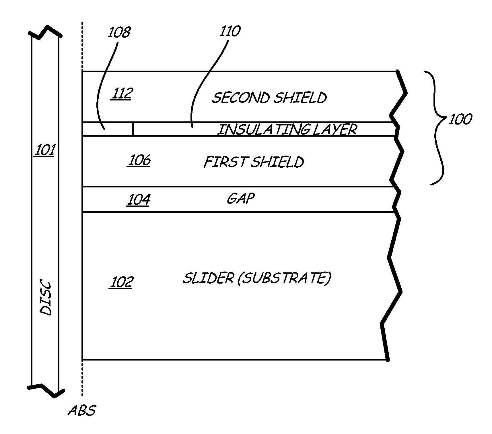
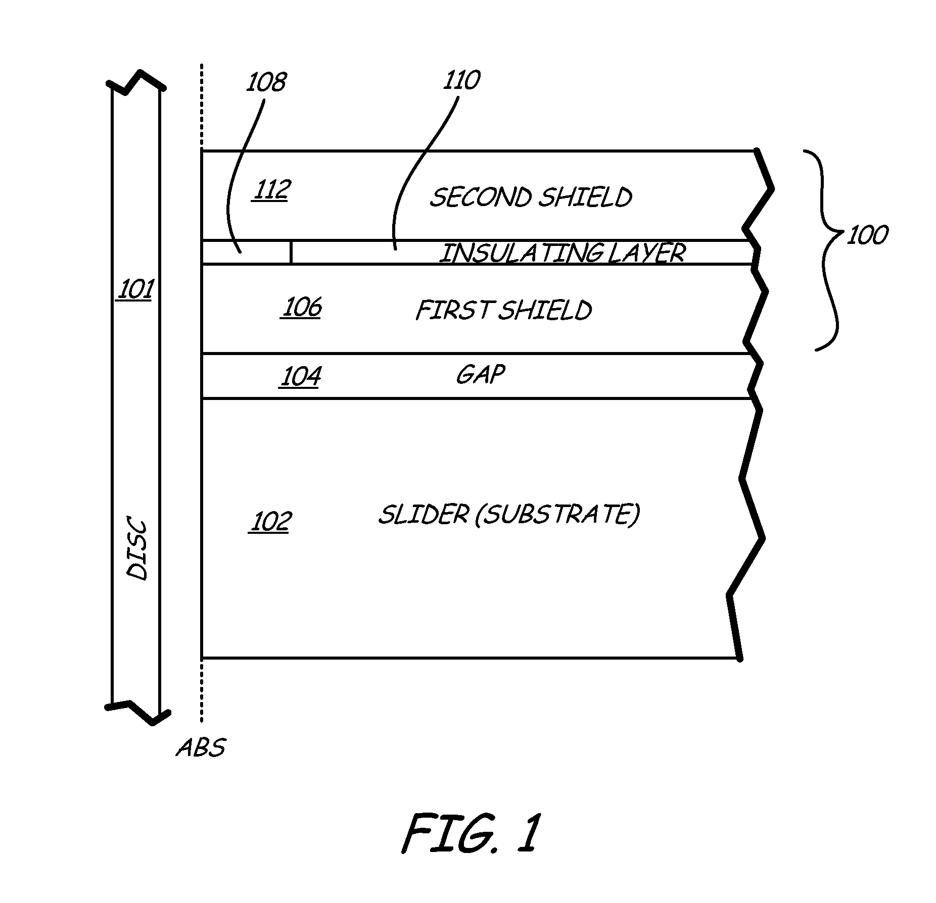
[0014]FIG. 1 is a cross-sectional view of magnetic read head 100 and magnetic disc 101 taken along a plane substantially normal to a plane of an air bearing surface (ABS) of magnetic read head 100. As will be described further below, the present embodiments are useful in a magnetic read head such as 100. Magnetic disc 101 may be either a perpendicular or longitudinal recording media, with magnetic read head 100 corresponding thereto. Magnetic read head 100 is carried on slider body (substrate) 102 and separated therefrom by gap 104. Magnetic read head 100 includes first magnetic shield 106, magnetoresistive (MR) sensor 108, insulating layers 110, and second magnetic shield 112. MR sensor 108 and insulating layers 110 are positioned between bottom and top shields 106 and 112, with MR sensor 108 being adjacent the ABS of magnetic head 100.

[0015]In the embodiment of FIG. 1, to provide current to MR sensor 108, first and second magnetic shields 106 and 112 perform double duty as both ma...


PUM


Abstract

An apparatus that includes a first read shield and a second read shield and a reader stack between the first and second read shields. The first and second read shields each include a thin high permeability layer closest to the reader stack and a low permeability layer and/or a geometric feature to control magnetic field flux lines in a free layer of the reader stack.

Description

BACKGROUND[0001]In a magnetic data storage and retrieval system, a magnetic recording head typically includes a reader portion, or read head, having a magnetoresistive (MR) sensor for retrieving magnetically encoded information stored on a magnetic medium, such as a magnetic disc. To help ensure that the MR sensor reads only the information that is stored directly beneath it on a specific track of the magnetic disc, magnetic shields are placed on the read head.[0002]As an ever-increasing amount of information is stored on a magnetic medium, it becomes difficult for MR sensors to separately read the stored information without also reading noise from adjacent stored information. Thus, as areal densities increase, there has to be a corresponding increase in sensitivity and resolution of the MR sensors.[0003]The present embodiments address these problems and offer other advantages over the prior art.SUMMARY[0004]In one embodiment, an apparatus that includes a first read shield and a sec...

Claims


Application Information

Patent Timeline
IPC IPC(8): G11B5/33
CPCG11B5/115Y10T428/11G11B5/3912
Inventor BENAKLI, MOURADRIVKIN, KIRILL ALEKSANDROVICHMACKEN, DECLANSAPOZHNIKOV, VICTOR BORIS
Owner SEAGATE TECH LLC
Why Eureka
Try Eureka