One-way or selectable clutch with multiple rows of ratchet elements

Inactive Publication Date: 2011-11-03
BORG WARNER INC
View PDF6 Cites 16 Cited by
  • Summary
  • Abstract
  • Description
  • Claims
  • Application Information

AI Technical Summary

Benefits of technology

[0017]In accordance with another aspect of the disclosure, a method of operating a clutch with reduced backlash and bi-directional capacity is disclosed which comprises providing a clutch assembly including of an inner race, an outer race, a locking arm, a cam surface, and a shoulder, rotating the inner race clo

Problems solved by technology

The one-way clutch is typically used in circumstances in which shaft to shaft, or shaft to race, rotational, torque-transferring engagements are desirable, but a “hard” connection such as a spline or keyed connection would not work.
Secondly, since the front wheels are also leading the vehicle through the curve, they must rotate faster than the rear wheels.
With a solid four-wheel drive engagement there is no device (such as a differential) to counter this action in and the slower moving rear wheels act in an undesirable braking manner.
Another undesirable four-wheel drive driving effect happens during engine braking.
The normal and undesirable parasitic affect of engine braking through the rear wheels of a manual transmission two-wheel drive vehicle has a negative impact on fuel consumption and efficiency, which is greatly increased in the case of four-wheel drive vehicles by adding in the front wheels as well.
While proving to be of great value, as transfer case design technology utilizing one-way clutches continues to evolve, the one-

Method used


Image

  • One-way or selectable clutch with multiple rows of ratchet elements
  • One-way or selectable clutch with multiple rows of ratchet elements
  • One-way or selectable clutch with multiple rows of ratchet elements

Examples


Example

[0027]While the present disclosure is susceptible to various modifications and alternative embodiments, certain illustrative embodiments thereof have been shown in the drawings and will be described below in detail. It is to be understood, however, that there is no disclosure to limit the present disclosure to the specific forms disclosed, but on the contrary, the intention is to cover all modifications, alternative constructions, and equivalents falling within the spirit and scope of the present disclosure.

DETAILED DESCRIPTION OF THE DISCLOSURE

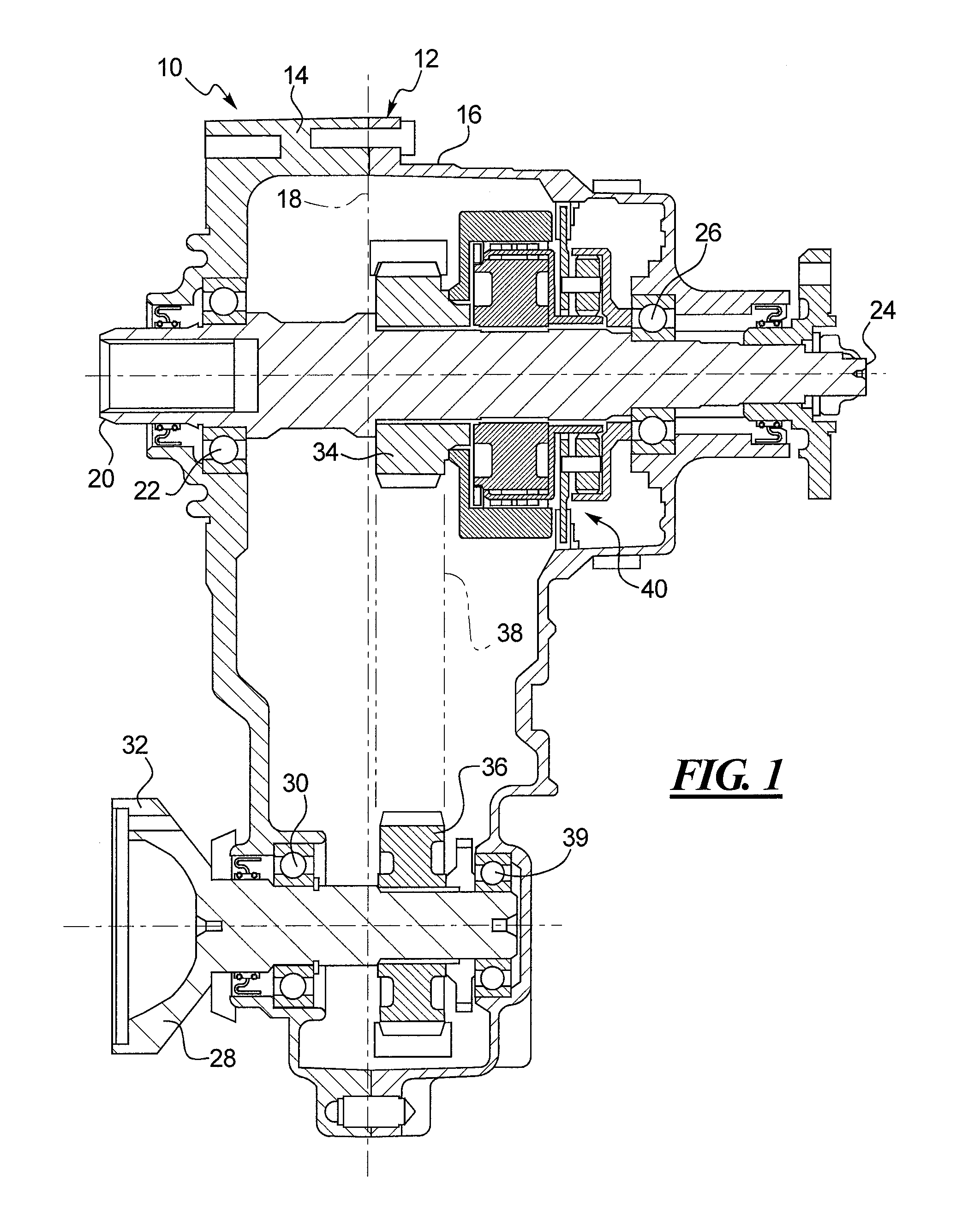
[0028]Referring now to the drawings and with specific reference to FIG. 1, a transfer case utilized in a four-wheel drive vehicle (not shown) and incorporating the present disclosure is generally referred to by reference numeral 10. The transfer case 10 includes a housing 12 which is formed by a case 14 and a cover 16 which mate along central line 18 in a conventional matter. An input shaft 20 is rotatably supported by an input roller bearing...


PUM


Abstract

A one-way or selectable clutch with multiple circumferential rows of ratchet elements is disclosed. The clutch may include two or more rows of ratchet elements extending between two or more races. The device may be either a one-way clutch or a selectable mechanical clutch, and afford the benefits of reduced backlash and multiple modes of operation. Those modes may include free-wheel/overrun in both clockwise and counterclockwise directions, lock/transmit torque in both directions, lock in clockwise and overrun in counterclockwise directions, and lock in counterclockwise and overrun in clockwise directions.

Description

CROSS-REFERENCE TO RELATED APPLICATION[0001]This application is a Patent Cooperation Treaty patent application claiming priority under 35 USC 119(e) to U.S. Provisional Patent Application No. 61,107,571 filed on Oct. 22, 2008.FIELD OF THE DISCLOSURE[0002]The present disclosure generally relates to clutch assemblies and, more particularly, relates to radial ratchet one-way and selectably-engageable clutches.BACKGROUND OF THE DISCLOSURE[0003]Transfer cases are used in full and part-time, four-wheel drive vehicles to distribute driving power received through an input shaft from the vehicle transmission to a pair of output drive shafts. One of the drive shafts powers the vehicle front wheels and the other drive shaft powers the vehicle rear wheels. In vehicles permitting shifting between two wheel drive and four wheel drive modes, the input shaft of the transfer case provides continuous power to one of its output shafts and selectively provides drive power to the other output shaft by s...

Claims


Application Information

Patent Timeline
IPC IPC(8): F16D41/12F16H7/00
CPCF16D41/125F16D41/16
Inventor PAPANIA, JAMES R.
Owner BORG WARNER INC
Why Eureka
Try Eureka