Heating and fluidization system for air fluidized sand beds

Inactive Publication Date: 2011-11-10
TYL THOMAS W
View PDF2 Cites 0 Cited by
  • Summary
  • Abstract
  • Description
  • Claims
  • Application Information

AI Technical Summary

Benefits of technology

[0018]In yet another exemplary embodiment, the technology described herein provides a method for simultaneous, independent control of both heating and fluidization in a heating and fluidization system for air fluidized sand beds. The method includes: providing at least one heating tube configured to receive a heat input from a heat source and to provide the heat input to a media in a bed at a first predetermined, optimized rate; providing at least one fluidization tube disposed, generally, below the heating tube and configured to provide a fluidization rate to the media in the bed at a second predetermined, optimized rate, thereby adapted to maximize heat transfer; applying the heat input to the media in the bed at the first predetermined, optimized rate; controlling the fluidization at the second predetermined, optimized rate, thereby maximizing heat transfer; and separating control of the heat input from control of the fluidization rate for optimizing simultaneously both the amount of heat entering the system and the heat transfer rate.
[0019]The method also can include, wherein the heat source comprises an electrical heating element disposed with the tube: providing a plurality of holes disposed within a circumferential side wall of the heating tube, the holes adapted for passage through which a gas at a level optimized for heat transfer can escape; maintaining, at the optimi

Problems solved by technology

It is extremely difficult to maximize heat transfer in an air fluidized sand bed.
When more heat is needed, burners fire harder and fluidization increases, generally lowering h

Method used


Image

  • Heating and fluidization system for air fluidized sand beds
  • Heating and fluidization system for air fluidized sand beds
  • Heating and fluidization system for air fluidized sand beds

Examples


Example

[0033]Before describing the disclosed embodiments of this technology in detail, it is to be understood that the technology is not limited in its application to the details of the particular arrangement shown here since the technology described is capable of other embodiments. Also, the terminology used herein is for the purpose of description and not of limitation.

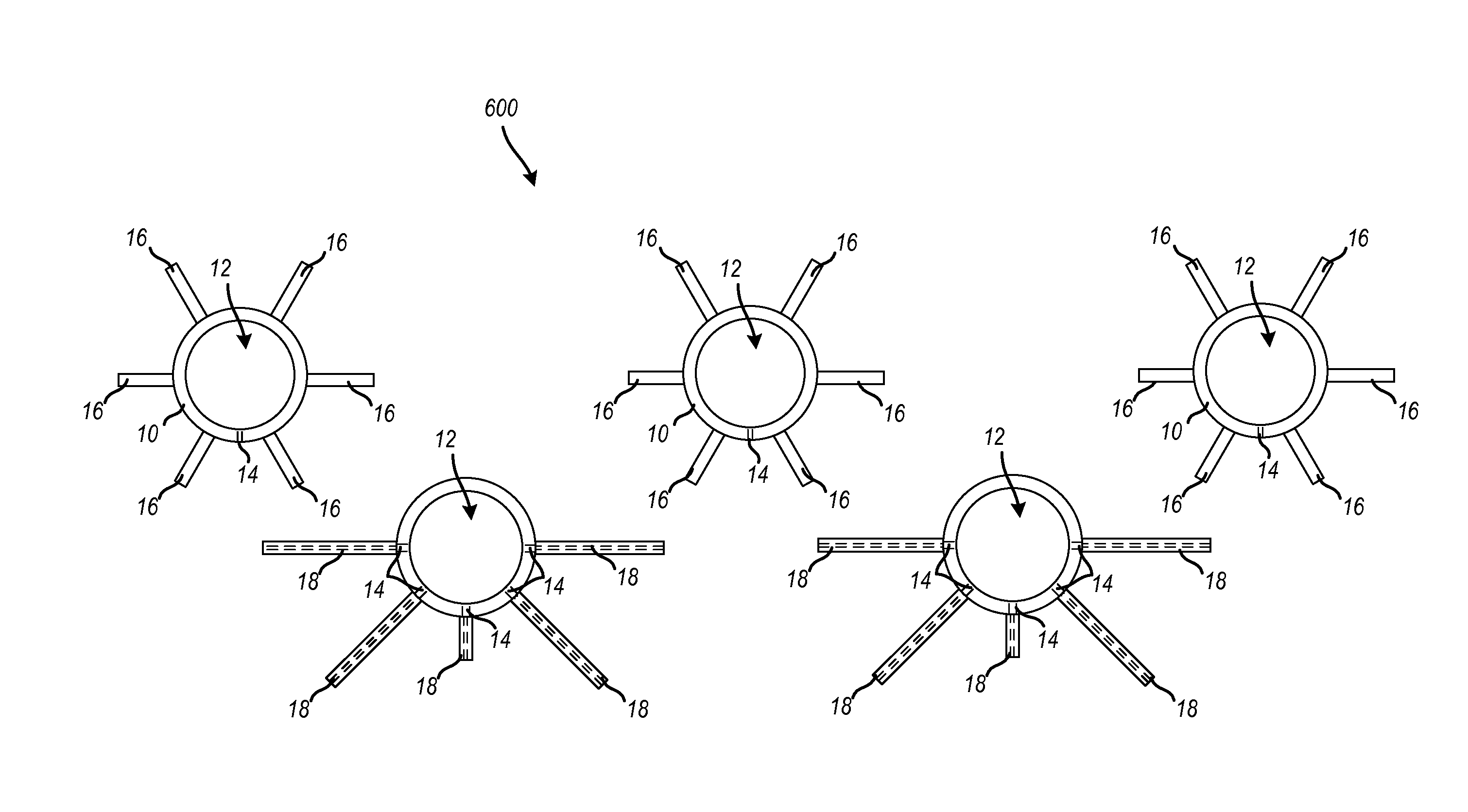
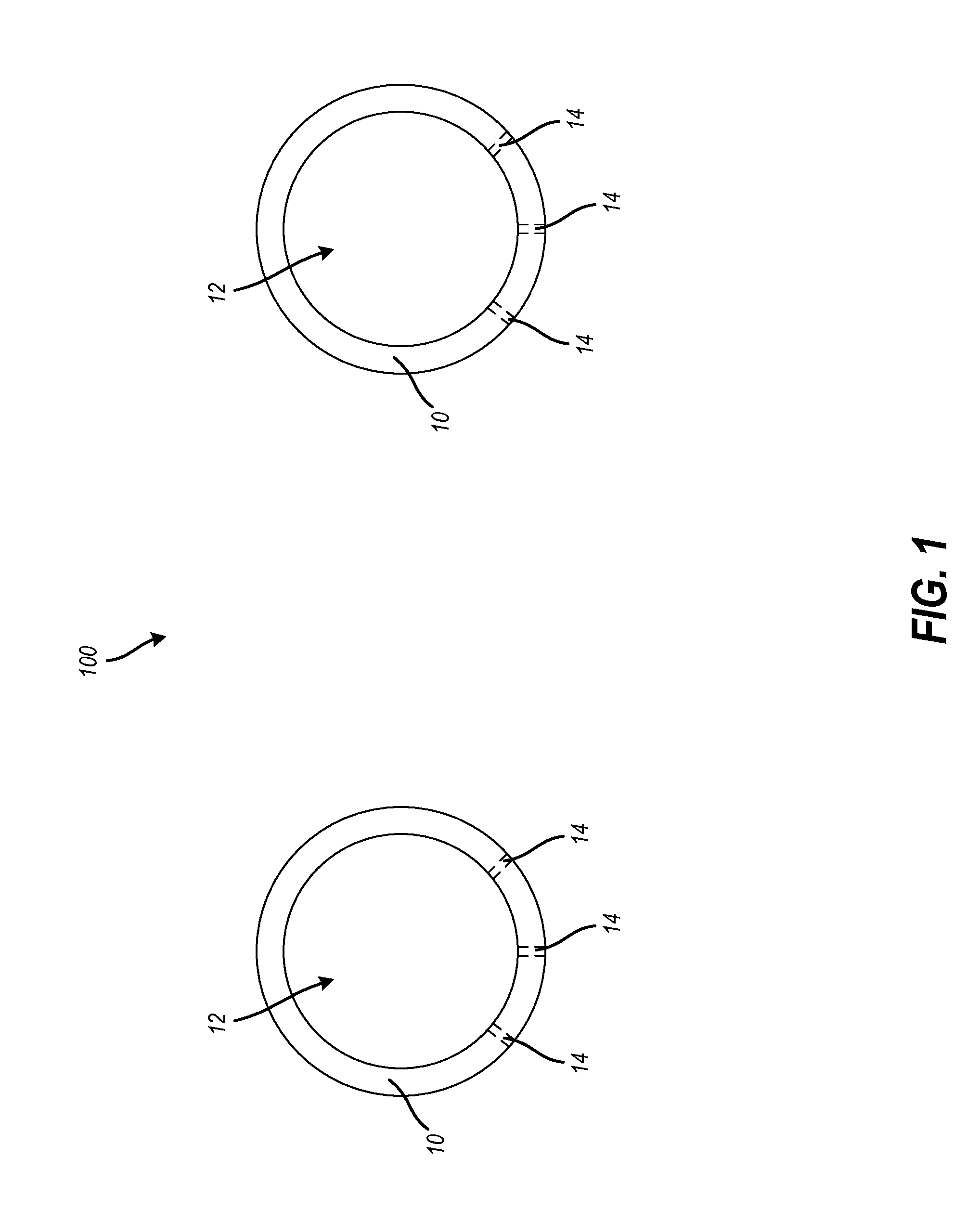
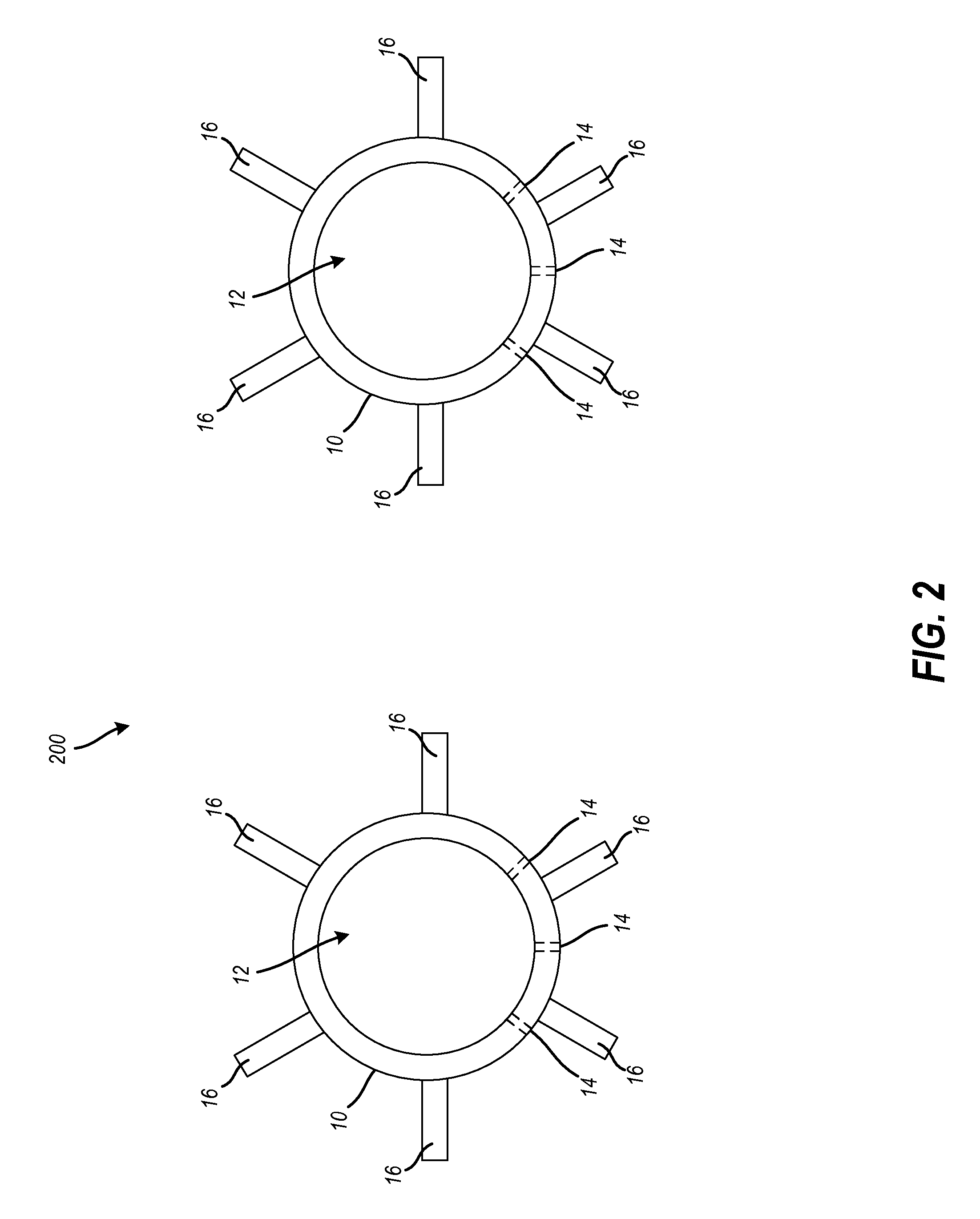
[0034]In various exemplary embodiments, the technology described herein provides for a heating and fluidization system for air fluidized sand beds and associated methods in which control of a heat input is separated from control of a fluidization rate to optimize simultaneously both the amount of heat entering the system and the heat transfer rate.

[0035]The driving force for heat treating is the difference in temperature between the material and the media. However, the rate of heat transfer in a fluidized bed is greatly influenced by the rate of fluidization of the sand (or media). If there is too much air in the sand heat...


PUM

PropertyMeasurementUnit
Pressureaaaaaaaaaa
Flow rateaaaaaaaaaa
Surface areaaaaaaaaaaa

Abstract

A heating and fluidization system for air fluidized sand beds, and associated methods, are disclosed. Control of a heat input is separated from control of a fluidization rate to optimize simultaneously both the amount of heat entering the system and the heat transfer rate. In at least one embodiment, the system includes: a heating tube configured to receive a heat input from a heat source and to provide the heat input to a media in a bed at a first predetermined, optimized rate; and a fluidization tube disposed, generally, below the heating tube and configured to provide a fluidization rate to the media in the bed at a second predetermined, optimized rate, thereby adapted to control fluidization and to maximize heat transfer. The heating tubes can include spines to increase surface area and maximize heat transfer. The fluidization holes can be covered by nozzles to direct the fluidization.

Description

FIELD OF THE INVENTION[0001]The technology described herein relates generally to the fields of heat treating and air fluidized sand beds. More specifically, the technology relates to a heating and fluidization system for air fluidized sand beds and associated methods in which control of a heat input is separated from control of a fluidization rate to optimize simultaneously both the amount of heat entering the system and the heat transfer rate.BACKGROUND OF THE INVENTION[0002]It is extremely difficult to maximize heat transfer in an air fluidized sand bed. Known air fluidized sand beds link the fluidization level and the amount of heat input. By way of example, known strand air fluidized sand beds, especially gas heated models, cannot disconnect heating from fluidization. When more heat is needed, burners fire harder and fluidization increases, generally lowering heat transfer rate. Some manufacturers are known to fire burners directly into fluidization tubes. However, such a proces...

Claims


Application Information

Patent Timeline
IPC IPC(8): H05B3/00
CPCC21D1/53F27B15/10F27B15/02
Inventor TYL, THOMAS W.
Owner TYL THOMAS W
Why Eureka
Try Eureka