Hydraulic reservoir with integrated heat exchanger

a technology of hydraulic reservoir and heat exchanger, which is applied in the direction of air heater, machine/engine, vehicle heating/cooling devices, etc., can solve the problems of increasing heat rejection and dissipation, and achieve the effect of minimizing cavitation in associated hydraulic components

Inactive Publication Date: 2008-12-02
PARKER INTANGIBLES LLC
View PDF19 Cites 20 Cited by
  • Summary
  • Abstract
  • Description
  • Claims
  • Application Information

AI Technical Summary

Benefits of technology

[0008]The present invention takes advantage of relatively large low pressure hydraulic reservoirs, and the thus large surface areas, to provide cooling in lieu of separate heat exchangers via the combination of the previously separate heat exchanger and low-pressure reservoir into a unitary component, thereby reducing system cost, weight and size, while increasing reliability.
[0009]The resulting system basically comprises a pressure vessel with spaced inner and outer shells forming an annular area (in cross-section) that is sized in accordance with projected flow rate requirements. The outer shell is provided with cooling fins to maximize the surface area exposed to air, thereby increasing heat rejection and the dissipation thereof. The outer shell additionally contains the several fluid ports required for hydraulic connections.
[0010]Specifically, in terms of structure, a first embodiment of the invention provides a hydraulic reservoir with integrated heat exchanger comprising: a. a generally cylindrical central section having an inner cylindrical shell portion and a peripherally-spaced cylindrical outer shell portion, with a first annular gap therebetween, the outer shell portion being provided with a plurality of external cooling fins; b. a bottom cap portion, closing the central section at a lower end portion thereof; c. a top cap portion, closing the central section at an upper end portion thereof, having an outer cap portion and a spaced inner cap portion, with a second gap therebetween forming a direct continuation of the central section first gap, the outer cap portion including a fluid inlet port in communication with the second gap; d. the, central section, together with the top and bottom cap portions, defining an internal central fluid cavity containing pressurized fluid; and e. a fluid supply / return port and at least one fluid outlet port extending into the central fluid cavity; wherein incoming fluid, into the fluid inlet port, flows from the second gap into and through the entire length of the first gap before entering the central fluid cavity, thereby maximizing heat transfer from the fluid via the plurality of external cooling fins.
[0017]In yet a differing variation, the hydraulic reservoir with integrated heat exchanger is mounted in a substantially vertical position, the substantially vertical configuration minimizing the possibility of fluid movement within the central fluid cavity, thereby minimizing the potential of cavitation of associated hydraulic pump / motor(s), with the substantially vertical configuration also maximizing heat exchange effectiveness due to the long vertical distance the fluid travels while in contact with the cylindrical outer shell portion.
[0023]In another variation, the reservoir with integrated heat exchanger is mounted in a substantially vertical position, the substantially vertical configuration minimizing the possibility of fluid movement within the central cavity, thereby minimizing cavitation in associated hydraulic components.

Problems solved by technology

The outer shell is provided with cooling fins to maximize the surface area exposed to air, thereby increasing heat rejection and the dissipation thereof.

Method used


Image

  • Hydraulic reservoir with integrated heat exchanger
  • Hydraulic reservoir with integrated heat exchanger
  • Hydraulic reservoir with integrated heat exchanger

Examples


Embodiment Construction

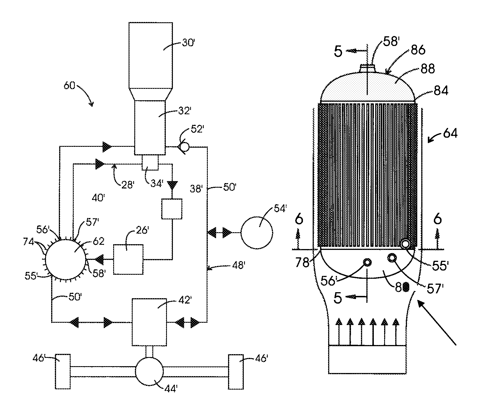
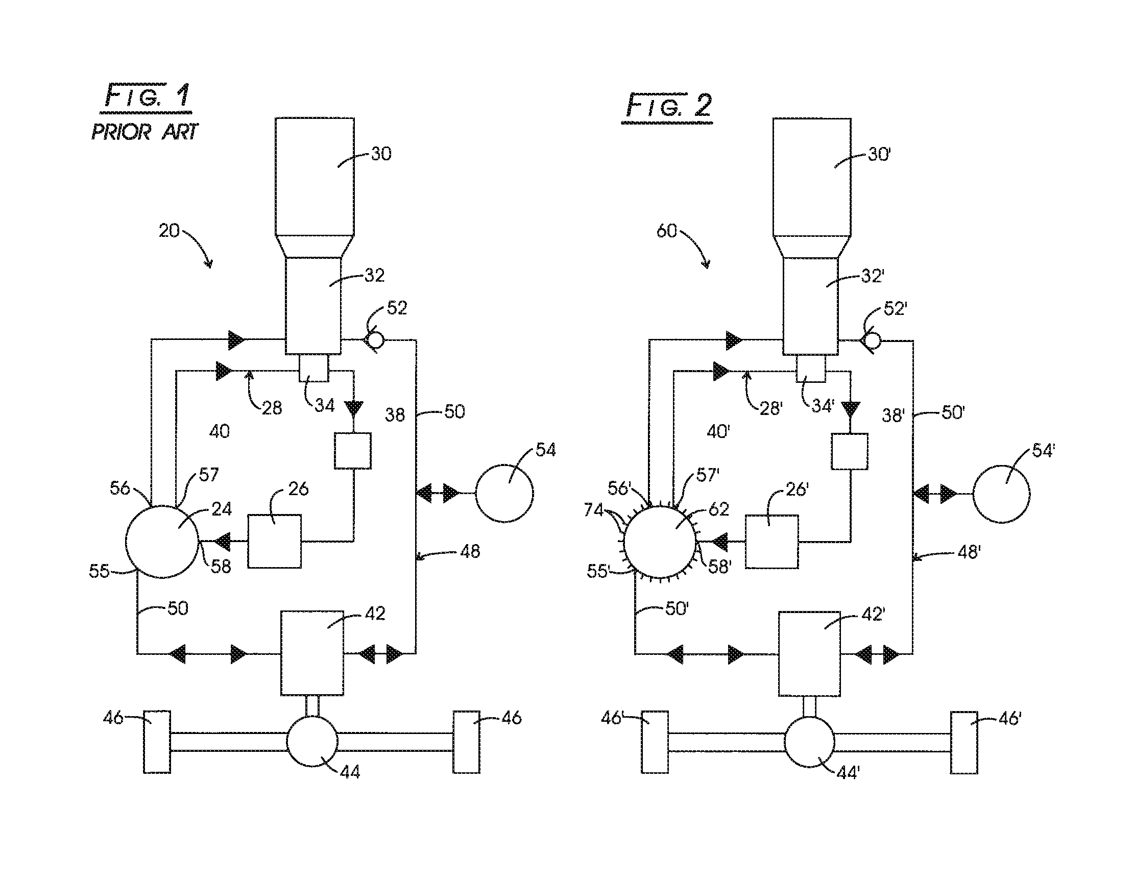
[0033]Referring now to the several drawings, illustrated in prior art FIG. 1 is a simplified system diagram, generally indicated at 20, of a known hydrostatic type of a hydraulic transmission for, as an example, a motor vehicle such as a highway truck, that utilizes both a low pressure hydraulic reservoir 24 and a separate liquid-to-air heat exchanger 26 in its transmission cooling circuit 28. Those skilled in the art will readily recognize that a prime mover 30, such as an internal combustion engine, drives a main hydraulic pump 32 which, in turn may also drive a separate cooling pump 34, if so desired. Interposed between cooling pump 34 and low pressure hydraulic reservoir 24 are heat exchanger 26 and, upstream thereof, a fluid filter 38. Items or components 24, 26, 34 and 38 are fluidically operatively interconnected via a line, conduit or bores 40 and together, comprise fluid cooling circuit 28.

[0034]System diagram 20 further illustrates the use of a pump / motor(s) 42 whose outpu...


PUM

PropertyMeasurementUnit
poweraaaaaaaaaa
lengthaaaaaaaaaa
shapeaaaaaaaaaa

Abstract

Improvement, in hydraulic systems, such as for vehicle transmissions and the like, in the form of a hydraulic reservoir with integrated heat exchanger having fluid supply / return and fluid return ports, including a central section, having inner and outer shell portions with a first gap therebetween, the outer shell being provided with a plurality of radially-spaced, external cooling fins, longitudinally-directed for the length of the central section; the ends of the latter being closed off via respective bottom and top cap portions, thereby defining a central fluid cavity, the top cap portion having spaced outer and inner cap portions, with a second gap therebetween, with a fluid inlet port, in the outer cap portion, directing incoming fluid from the second gap into and through the entire length of the first gap before entering the central fluid cavity, thereby maximizing heat transfer from the fluid via the plurality of cooling fins.

Description

CROSS-REFERENCE TO RELATED CASES[0001]The present application claims the benefit of the filing date of U.S. Provisional Application Ser. No. 60 / 590,262, filed Jul. 22, 2004, the disclosure of which is incorporated herein by reference.FIELD OF THE INVENTION[0002]The present invention pertains to a hydraulic reservoir with integral heat exchanger (HRwiHE), for use, for example, in hydraulic transmissions for trucks and the like, with the HRwiHE being part of the hydraulic cooling circuit. More particularly, the HRwiHE utilizes a plurality of external cooling fins, associated with a central section of the HRwiHE to maximize the heat transfer from the working fluid.BACKGROUND OF THE INVENTION[0003]Hydraulic or hydrostatic transmissions, for example, for on-highway vehicles such as trucks, have received greater interest in recent years as the price of fuel has increased sharply. Hydrostatic transmissions (HSTs) have an advantage over conventional hydrodynamic and gear transmissions in re...

Claims


Application Information

Patent Timeline
Patent Type & Authority Patents(United States)
IPC IPC(8): F28D7/02
CPCF15B1/26Y10S60/912Y10S165/916
Inventor SIMON, MATTHEW H.
Owner PARKER INTANGIBLES LLC
Why Eureka
Try Eureka