Exhaust throttling for cabin heating

a cabin heating and exhaust throttling technology, applied in the field of system for heating a cabin, can solve the problems of waste of fuel and inefficient methods, and achieve the effect of promoting efficient cabin heating and maximizing heat transfer

Active Publication Date: 2015-05-07
FORD GLOBAL TECH LLC
View PDF5 Cites 22 Cited by
  • Summary
  • Abstract
  • Description
  • Claims
  • Application Information

AI Technical Summary

Benefits of technology

[0003]The inventors have recognized that exhaust heat whose route is altered by throttling the exhaust may be recovered and directly routed to the cabin heating system rather than indirectly routed to the cabin heating system via the engine coolant system. Further, the inventors have also recognized that by varying the flow rate of coolant into the cabin heating system as the characteristics of the system (e.g., coolant temperature, blower fan speed, etc.) change, an optimal amount of heat may be transferred from the exhaust to the cabin heating system. Accordingly, a method for an engine is provided, comprising pumping coolant from a coolant reservoir to an exhaust component and then to a heater core, the coolant heated by the exhaust component, and during engine warm-up conditions, adjusting a flow rate of coolant into a heater core to maximize heat transfer to a vehicle cabin.
[0004]In one example, the coolant is sourced from the engine's general coolant system, passes through a heat pick up element (e.g., EGR cooler) and then passes through a heat sink (the heater core), and is released into the engine's general coolant system. During non-steady state conditions, such as when the engine is heating up, there is a coolant flow rate (that is not necessarily the maximum flow rate) that achieves maximum heat transfer into the heater core. That coolant flow rate is a function of the heater core temperature drop (ΔT). The maximum heat is transferred when the product of ΔT and flow rate are maximized. However, during steady state conditions, such as when the engine has reached operating temperature, the coolant may be flowed at a constant flow rate, such as maximum flow rate. In this way, as the system characteristics change during engine warm-up, the flow rate may be continually adjusted to maintain maximum heat transfer to the cabin and thus promoting efficient cabin heating.

Problems solved by technology

However, such a method is energy inefficient and wastes fuel, as only a small fraction of the exhaust heat appears in the engine coolant.

Method used


Image

  • Exhaust throttling for cabin heating
  • Exhaust throttling for cabin heating
  • Exhaust throttling for cabin heating

Examples


Embodiment Construction

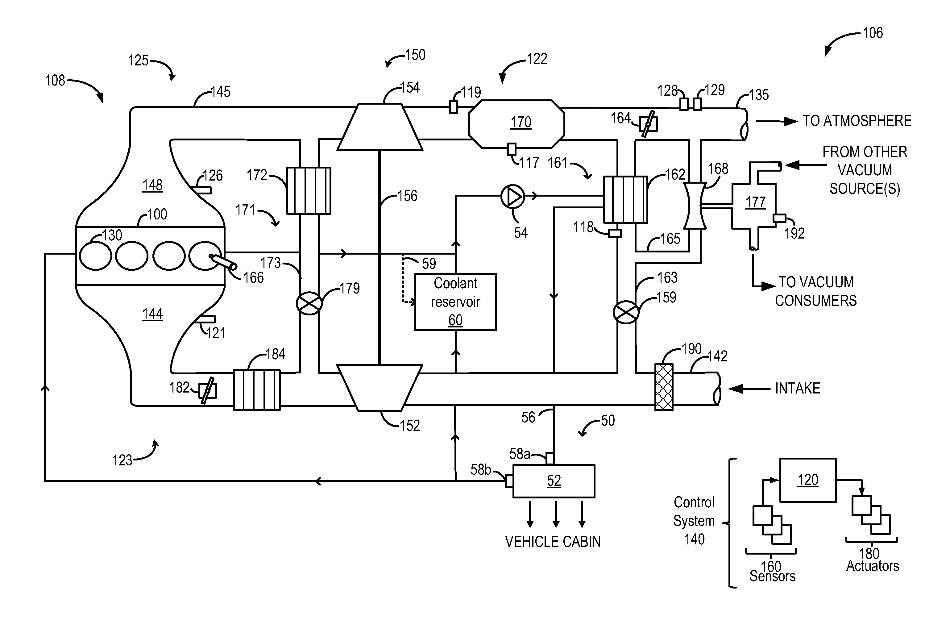
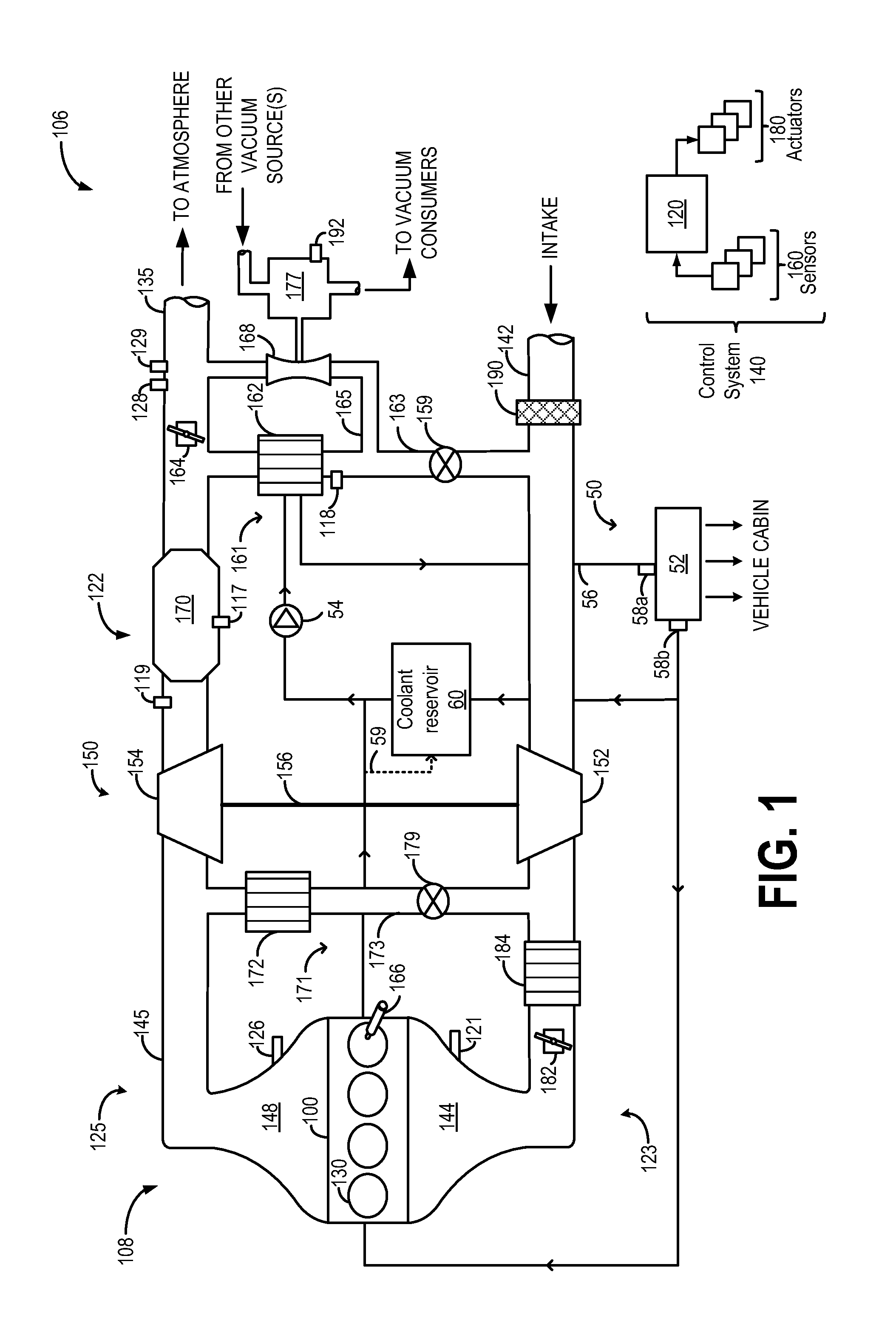
[0012]Methods and systems are provided for expediting heater core warm-up in a vehicle engine, such as the engine system of FIG. 1. During an engine cold-start and warm-up, synergistic benefits of increased exhaust backpressure and subsequent heat rejection at an EGR cooler may be advantageously used to quickly raise coolant temperature provided to the heater core. The conventional approach to getting heat out of the exhaust and into engine coolant includes maximizing the coolant flow rate and minimizing the coolant volume (via isolating coolant branches such as the branch into the radiator).

[0013]However, in the claimed configuration, the coolant is sourced from the engine's general coolant system, passes through the heat pick up element (EGR cooler) and then passes through the heat sink (heater core), and is released into the engine's general coolant system. In this case, there is a given coolant flow rate that achieves maximum heat transfer into the heater core. That coolant flow...


PUM


Abstract

Embodiments for heating a vehicle cabin are disclosed. In one example, a method for an engine comprises pumping coolant from a coolant reservoir to an exhaust component and then to a heater core, the coolant heated by the exhaust component, and during engine warm-up conditions, adjusting a flow rate of coolant into a heater core to maximize heat transfer to a vehicle cabin.

Description

FIELD[0001]The present disclosure relates to a system for heating a cabin of a motor vehicle.BACKGROUND AND SUMMARY [0002]Rapid cabin heating of a motor vehicle is desired, particularly during cold ambient conditions, to provide passenger comfort. Classically, cabin heat comes from the engine coolant, which may be heated indirectly via a massive increase in exhaust heat. However, such a method is energy inefficient and wastes fuel, as only a small fraction of the exhaust heat appears in the engine coolant.[0003]The inventors have recognized that exhaust heat whose route is altered by throttling the exhaust may be recovered and directly routed to the cabin heating system rather than indirectly routed to the cabin heating system via the engine coolant system. Further, the inventors have also recognized that by varying the flow rate of coolant into the cabin heating system as the characteristics of the system (e.g., coolant temperature, blower fan speed, etc.) change, an optimal amount...

Claims


Application Information

Patent Timeline
Patent Type & Authority Applications(United States)
IPC IPC(8): F01N5/02
CPCF01N5/02B60H1/04Y02T10/12B60H1/00
Inventor PURSIFULL, ROSS DYKSTRA
Owner FORD GLOBAL TECH LLC
Why Eureka
Try Eureka