Heating apparatus

a technology of heating apparatus and apertured emitter, which is applied in the direction of muffle furnaces, domestic stoves or ranges, furnaces, etc., can solve the problems of poor heating efficiency of apertured emitters, insufficient surface area of optimized heat, and insufficient heat transfer efficiency of apertured walls, so as to maximize heat transfer and maximize heat transfer. the effect of heat transfer from the hot combustion gas to the external wall portions

Inactive Publication Date: 2006-08-08
WATERS
View PDF49 Cites 25 Cited by
  • Summary
  • Abstract
  • Description
  • Claims
  • Application Information

AI Technical Summary

Benefits of technology

[0010]In accordance with the present invention, a high efficiency heating apparatus is provided that includes a heating head having flue chambers for the hot gases of combustion generated by operation of the burner assembly. In one form, the flue chambers are formed by external and internal wall portions of the head, and insulation material is provided along the internal wall portions so that heat transfer from the hot combustion gases to the external wall portions is maximized. In another form, the flue chambers are substantially isolated from each other and are configured to confine gas flow such that turbulent flow conditions are generated therein to maximize heat transfer from the gas to the heating head. In a preferred form, the heating apparatus is used as a patio heater with the heating head mounted on top of an elongate support member or pole. With the flue chambers as described above, the heating head can be maximized in size along its longitudinal axis allowing the pole length to be kept to a minimum.
[0011]In another aspect, the outer wall portion of the heating head are of a predetermined material selected to optimize the generation of infrared (IR) heat energy when heated. With heat transfer to these walls maximized, the axial head size can be increased, as earlier mentioned. Further, with the IR optimized outer wall material, e.g. aluminized or carburized steel, the head can be axially longer and still generate heat energy in the desired infrared region.
[0013]It is preferred that the outer wall becomes heated by the hot flowing gases of combustion in the flue chambers such that it emits radiant energy that is predominantly of infrared wavelength from its exterior surface into the surrounding area. To this end, the preferred heating apparatus is an excellent infrared radiation source in that the outer wall of the heating head is of a material having high emissivity properties in the region of infrared wavelengths. Moreover, since the outer wall is undulated in configuration, it effectively offers an increased amount of surface area available to emit radiant energy into the surrounding area. These and other features of the preferred heating apparatus permit substantial infrared radiant energy to be emanated into the surrounding vicinity of the heater. Due the resulting increased heating efficiencies of the heating apparatus, lower feed gas requirements are needed to obtain a given amount of heating effect, which translates into lower operating costs for the heater. As a result, the gas orifices of the burner assembly can be smaller than the conventional 48 gauge orifices, e.g. 52 or 54 gauge, and the heat input energy can be significantly reduced such as by approximately 50% cover current patio heaters, e.g. from approximately 40,000 BTU / hr to approximately 20,000 BTU / hr.
[0014]The heating apparatus also is effectively wind-proofed because the outer wall feature of the housing that constitutes the radiant energy emitter of the burner assembly can be deployed as a substantially continuous solid member preferably with little or no aperturing thereof that would otherwise permit ingress of winds sufficient to put out the flames of the burner assembly or premature egress of combustion gases before they reach the open-ended top of the housing. In addition, the use of a solid, non-foraminous or essentially non-foraminous outer wall construction also creates narrow enclosed annuluses or isolated flue chambers between the inner wall and outer wall of the emitter which are relatively small in cross-section, to create turbulent, non-laminar flow in the combustion gases as they pass upward through the annular spaces away from the burner assembly. The turbulent flow created in the hot combustion gases increases the amount of heat transfer from the gases to the outer wall. As the annular spaces provided for channeling combustion gases up through the housing are relatively narrow and relatively air-tight, and not wide in cross-section, the hot combustion gases have no or little opportunity to spread out and assume a laminar flow profile as they are funneled up the individual annular spaces until escaping at the respective open tops of the annular spaces which can be located immediately below a reflector dome or lid when the heating apparatus is used as a patio heater, for instance.
[0016]In one particular aspect, the heating apparatus in accordance with the present invention emits a significant proportion, such as 50% or more, of its generated radiant energy as infrared radiation. Moreover, it also emits a significantly higher percentage, such as 30% or more, of the heat input into the heater apparatus as radiant energy in the infrared region of the electromagnetic spectrum, as compared to conventional patio heaters. This high level of IR radiant energy generated by the heaters of the invention is highly useful and efficient for heating the bodies and or apparel worn by persons and patrons located around the heater.

Problems solved by technology

For example, patio beaters have become especially popular in recent years in areas such as the Southwest where no smoking laws are being applied to taverns and bars forcing patrons outdoors to smoke which can be especially inconvenient during cold nights.
A shortcoming of patio heaters using apertured emitters is their relatively poor heating efficiency.
Generally, the burner flames and the hot gaseous combustion products generate heat, and the current emitter heads are not in heat conducting relation with these heat sources for sufficient time as the heat energy passes through the apertured walls thereof.
In other words, the apertured walls lacked sufficient surface area in optimized heat transfer relation with the heat generated by the burner assembly.
Even in prior elongated and fluted solid heater casing constructions, see U.S. Pat. No. 2,950,713 to Sterick, the hot gaseous flow is not well confined for maximized heat transfer to the casing.
In addition, heat is lost to the interior of the casing in the '713 patent further reducing heat transfer efficiencies.
Accordingly, the heater of the '713 patent is not well-suited for high efficiency heating operations.
Although the apertured cylindrical walls on conventional heaters generate some radiant heat upon being heated up by the passing burner gases, the amount is relatively limited in reality.
The poor heating efficiency is attributable in part to the use of stainless steel and the like as the structural material of the apertured emitter wall of the conventional patio heaters.
What has not been previously appreciated is that such emitters generate radiant heat predominantly at relatively shorter wavelengths of the electromagnetic spectrum that are not very efficient for heating bodies and or apparel worn by people in the vicinity of the patio heater.
However, it has not been previously appreciated that the radiant energy generated by the heated stainless steel emitters includes only a small proportion falling in longer wavelength bands, such as far infrared waves.
As another drawback associated with conventional patio heaters, the apertured emitters used in conventional patio heaters have poor wind tolerance.
This leads to the loss of the heating effect until the burner flame can be re-ignited.
The cost of many conventional patio heaters has been increased due to the necessity of equipping them with automatic shut-off mechanisms for handling inadvertent occurrences of flame-out at the burner assembly.

Method used


Image

  • Heating apparatus
  • Heating apparatus
  • Heating apparatus

Examples


Embodiment Construction

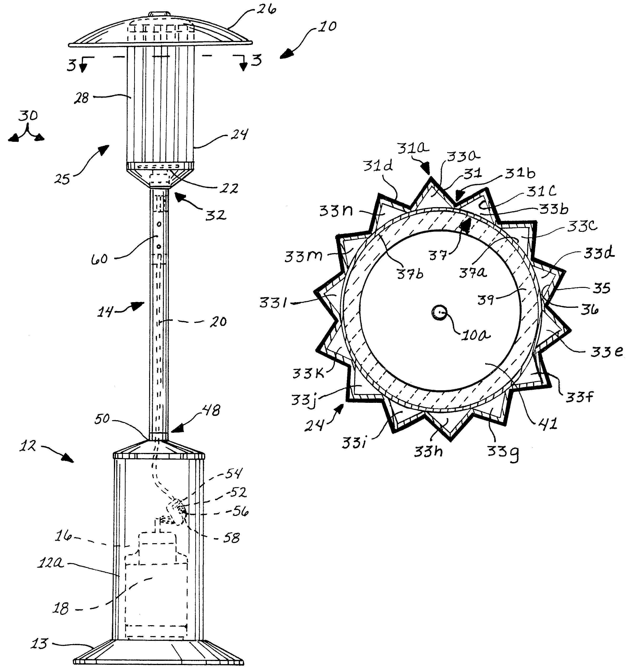
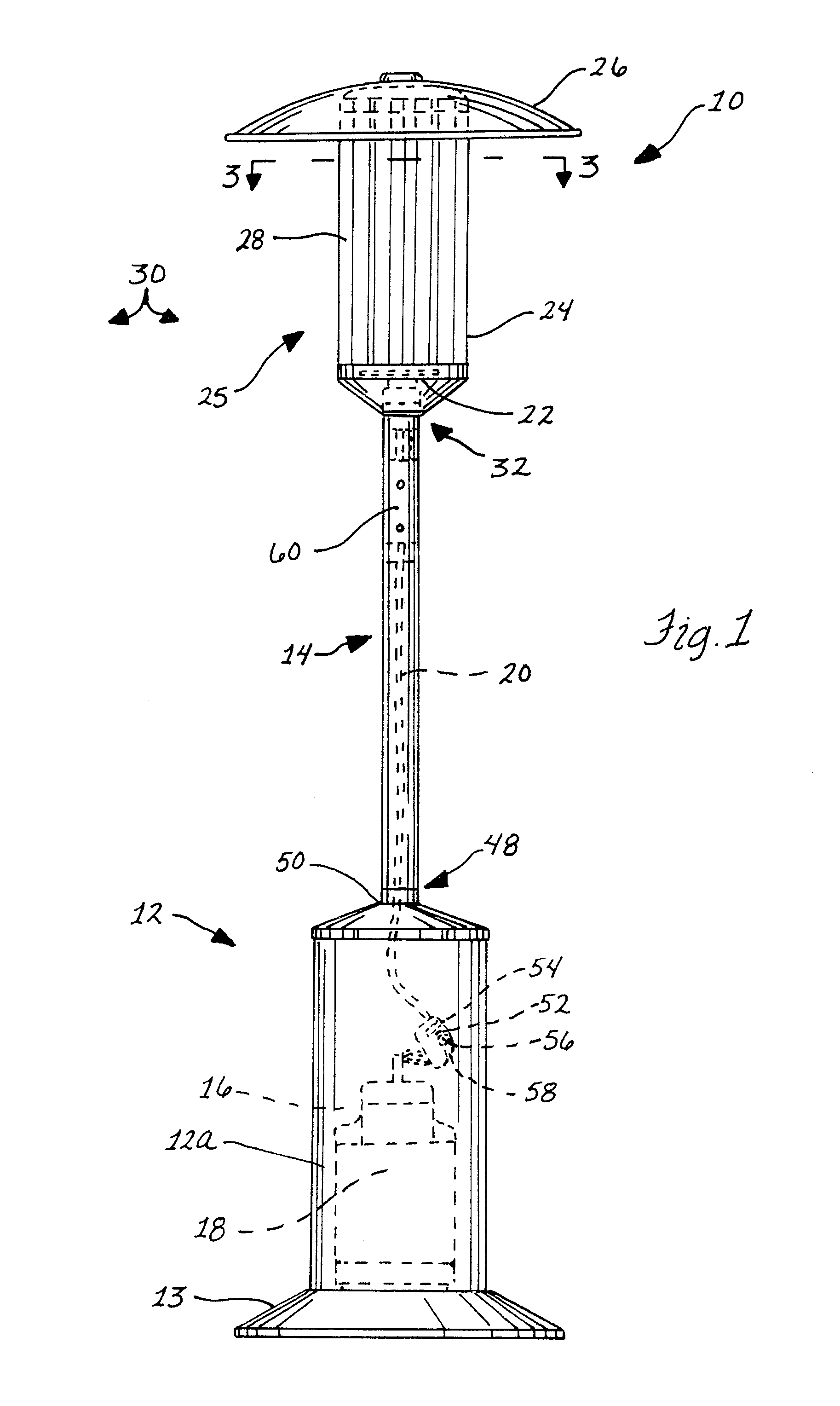
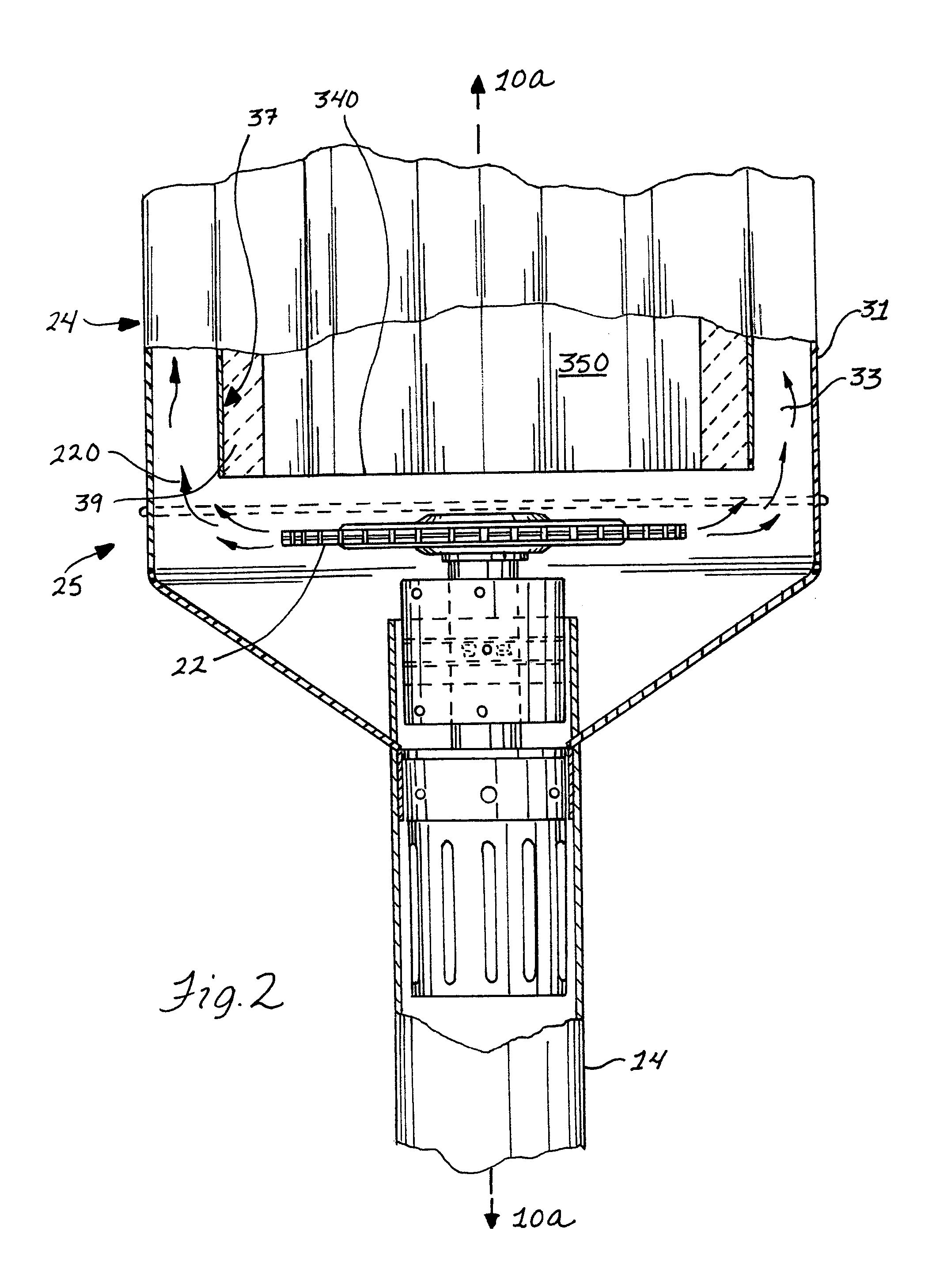
[0024]In FIGS. 1–4, a high-efficiency heating apparatus in accordance with the present invention is illustrated. The heating apparatus 10 is adapted to utilize natural or LP gas as fuel to generate heated air by the hot gases of combustion and radiant infrared heat for keeping an area about the apparatus 10 heated. The apparatus 10 is often termed a “patio heater” as it is designed primarily for outdoor use such as during nighttime in patio areas outside of taverns and bars so that patron can spend time outdoors in a comfortable preselected area which is warmer than the colder outdoor temperature. As shown, the patio heater 10 has a base 12 at the bottom of elongate support member, post or standard 14. The base 12 has an interior space 16 for containing L.P. tank 18 therein. Alternatively, the heating apparatus 10 need not be in the form of a patio heater including the base 12 and standard 14 described above, and instead can be more simply a free standing heating unit such as a spac...


PUM


Abstract

A heating apparatus is provided that is optimized in terms of its heating efficiencies and wind proofing against flame out. The heating apparatus includes a heating head and a burner assembly for igniting fuel from a fuel source. The heating head has a dual-walled construction to form several flue chambers with the inner wall preferably being insulated to maximize heat transfer to the outer wall from combustion gases flowing through the flue chambers. The flue chambers can also be formed to be substantially isolated from each other and configured to generate turbulent gas flow therein for maximum heat transfer to the outer wall.

Description

FIELD OF THE INVENTION[0001]The present invention generally relates to a heating apparatus and, more particularly, to a high efficiency heating apparatus for warming an area thereabout.BACKGROUND OF THE INVENTION[0002]LP propane or natural gas fueled heaters such as patio heaters are available in both free-standing and built-in configurations, and are primarily sold for commercial applications. For example, patio beaters have become especially popular in recent years in areas such as the Southwest where no smoking laws are being applied to taverns and bars forcing patrons outdoors to smoke which can be especially inconvenient during cold nights. Patio heaters can be utilized to provide warmth in preselected outdoor areas making it much more comfortable for smokers, and for those who like to be outdoors.[0003]Free-standing patio heaters that can be readily moved from location to location to heat preselected areas typically have a base that is sized to contain a fuel tank therein and ...

Claims


Application Information

Patent Timeline
Patent Type & Authority Patents(United States)
IPC IPC(8): F24C15/22F24C1/12F27B5/14
CPCF24C1/12
Inventor WATERS, MICHAEL
Owner WATERS
Why Eureka
Try Eureka