

Printhead and printing apparatus
a printing apparatus and printing head technology, applied in printing, inking apparatus, other printing apparatus, etc., can solve the problems of generating print signal transfer errors, electrical reliability drops, production costs rise, etc., and achieve the effect of improving the reliability of printing operation
- Summary
- Abstract
- Description
- Claims
- Application Information
AI Technical Summary
Benefits of technology
Problems solved by technology
Method used
Image

Examples
first embodiment
[0060]FIG. 4 is a block diagram showing the circuit arrangement of a printhead 101 according to the first embodiment.
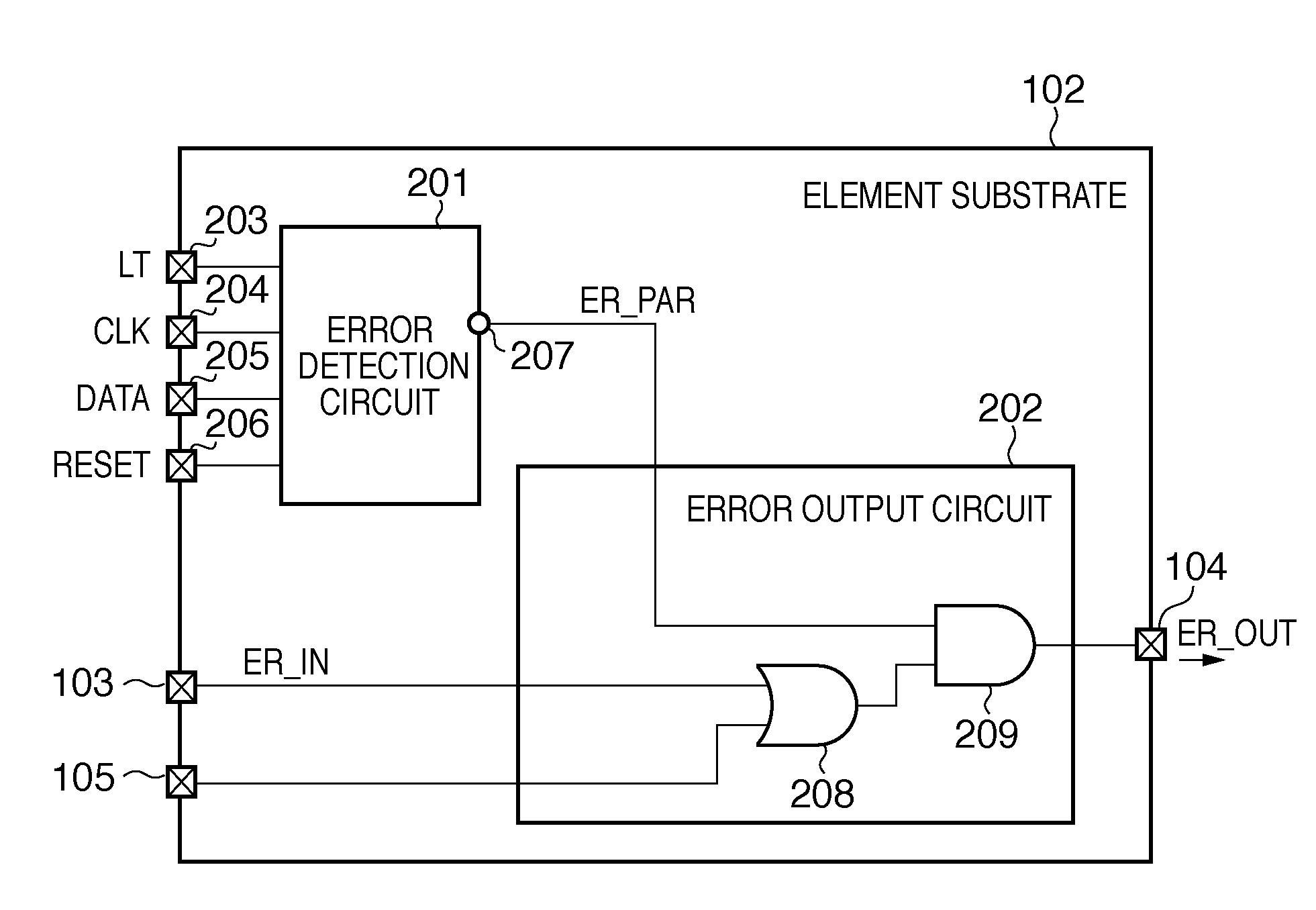
[0061]To achieve a large printing width, the printing width of the whole printhead 101 is increased by cascade-connecting a plurality (N) of element substrates 102. The element substrates 102 employ the same arrangement, and each of them has a terminal 103 for receiving information ER_IN of an element substrate on the preceding stage, and a terminal 104 for outputting information ER_OUT to an element substrate on the next stage. A terminal 105 of an element substrate on the first stage (leftmost stage in FIG. 4) among the cascade-connected element substrates is connected to an input pad 110 for inputting power VDD supplied from outside the printhead. The terminals 105 of the remaining element substrates are grounded. In correspondence with the number of element substrates, the printhead 101 has terminals 107 for inputting a print data signal DATA. In the first embodim...
second embodiment
[0079]FIG. 9 is a block diagram showing the arrangement of an error output circuit 202 according to the second embodiment. In FIG. 9, the same reference numerals as those in the arrangement described in the first embodiment with reference to FIG. 5 denote the same parts, and a description thereof will not be repeated. In FIG. 9, the error output circuit 202 receives a clock check signal CLK CHECK for checking reception of the clock signal CLK and latch signal LT. A check signal output circuit 210 outputs the clock check signal CLK CHECK based on the logic level of check data CHK contained in a predetermined bit of the print data signal DATA. For example, if the logic level of the check data is “high”, the check signal output circuit 210 outputs a high-level clock check signal CLK CHECK.
[0080]If the logic level of the check data CHK is “low”, the check signal output circuit 210 outputs a low-level clock check signal CLK CHECK. To perform this control, the gate array 1704 sets the log...
third embodiment
[0092]FIG. 11 is a block diagram showing the arrangement of an element substrate according to the third embodiment. In FIG. 11, the same reference numerals as those described in the first and second embodiments denote the same parts, and a description thereof will not be repeated. As is apparent from FIG. 11, the third embodiment has a feature in which the element substrate includes an error history save 1-bit memory (to be referred to as a memory) 221 for saving an error detection result ER_PAR output from the error detection circuit 201. The memory 221 outputs a memory content ER_MEM to the outside via a tristate buffer 222 and terminal 223. The tristate buffer 222 receives, via a terminal 220, a signal ER_SEL which is supplied from the printing apparatus main body and designates output.
[0093]FIG. 12 is a block diagram showing an arrangement in which the content ER_MEM of the memory 221 is output outside the printhead. The printhead is constructed by connecting a plurality of elem...
PUM
 Abstract
Description
Claims
Application Information