X-ray ct apparatus and method

a technology of ct and x-ray, applied in the field of ct apparatus, can solve the problems of excessive or deficient x-ray amount, and achieve the effect of high-quality

Active Publication Date: 2011-11-10
FUJIFILM HEALTHCARE CORP
View PDF1 Cites 16 Cited by
  • Summary
  • Abstract
  • Description
  • Claims
  • Application Information

AI Technical Summary

Benefits of technology

The present invention can provide an X-ray CT apparatus capable of acquiring a high-quality CT image by appropriately setting the bed position or a change pattern of the tube current during scanning according to the positional displacement between the subject and a compensation filter.

Problems solved by technology

When the X-ray tube current is constant as a scanning condition of the X-ray CT apparatus, the amount of X-rays may be excessive or deficient depending on the emission angle or an emitted portion of X-rays.

Method used


Image

  • X-ray ct apparatus and method
  • X-ray ct apparatus and method
  • X-ray ct apparatus and method

Examples


first embodiment

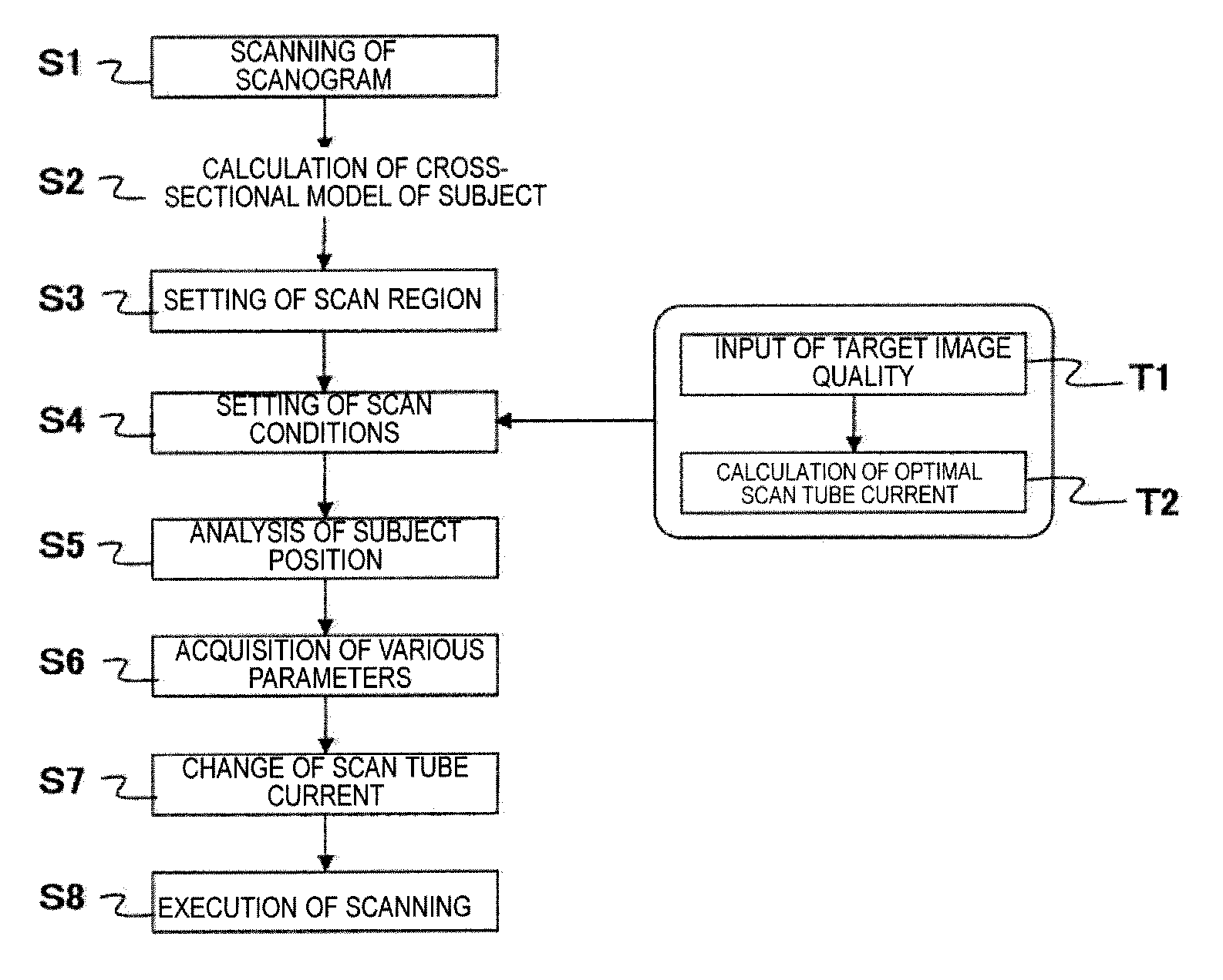
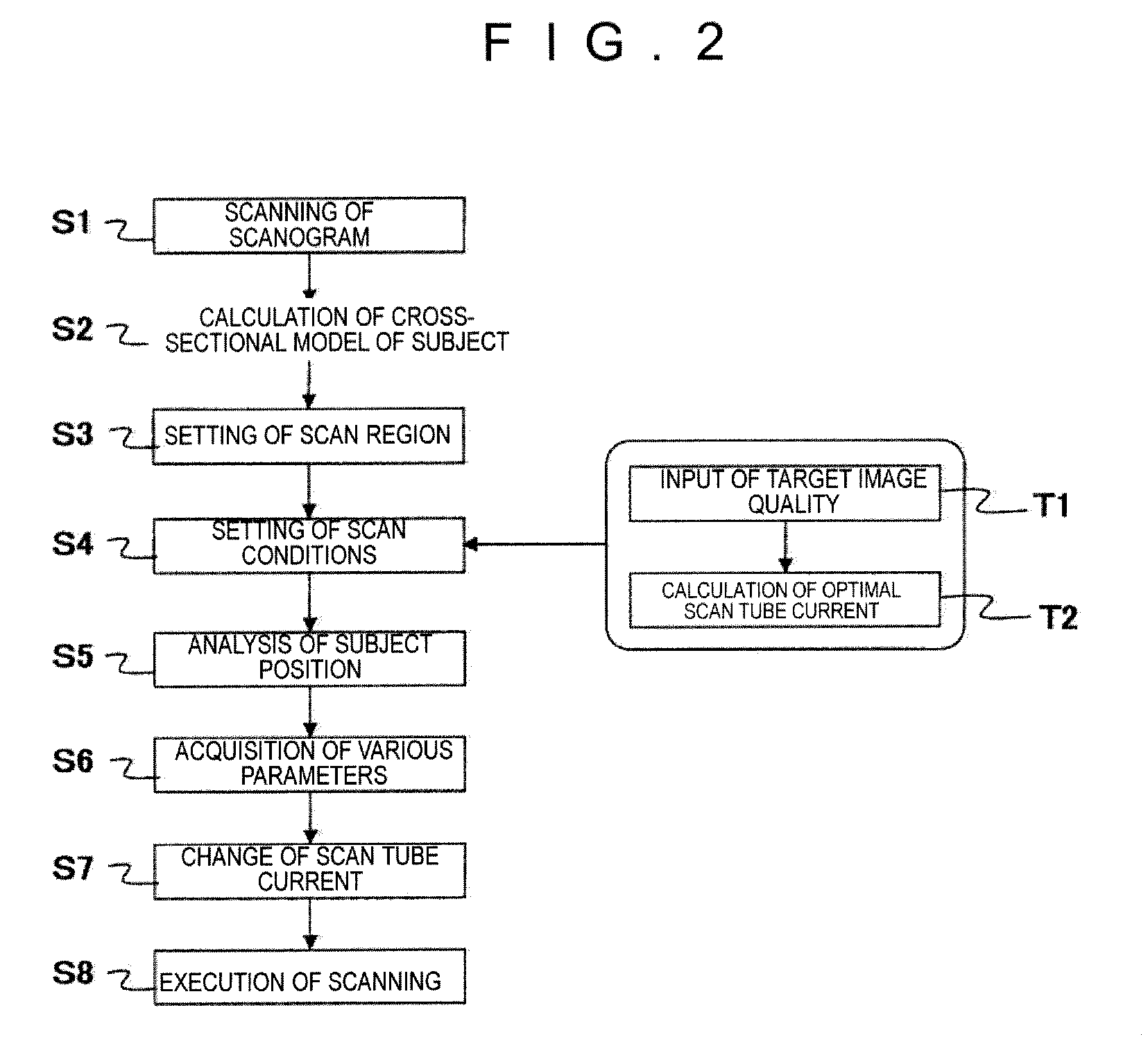
FIG. 2 shows a flow chart of a series of operations in scanning (scanning) related to a first embodiment of the present invention. Hereinafter, each step in FIG. 2 will be described in the order of the steps.

(Step S1)

The X-ray CT apparatus 1 acquires the scanogram projection data by performing scanogram scanning of the subject under control of the system controller 124 and creates a scanogram image. X-rays are emitted to the subject in one direction (for example, from the back to the front) without rotating the X-ray tube, and the scanogram projection data is acquired by the detector. The X-ray CT apparatus 1 creates a scanogram image by transmitting the scanogram projection data to the image operation device 122 and displays it on the display device 125. This scanogram image is created when an image of X-rays transmitted from the back to the front is viewed from one direction, for example.

(Step S2)

Then, the scanogram projection data is analyzed by a cross-sectional model calculatin...

second embodiment

Next, a second embodiment will be described using the operation flow chart in FIG. 7. The operation flow in the second embodiment is basically the same as that in the first embodiment. However, in the case of a bed of an X-ray CT apparatus used in the present embodiment, not only horizontal movement (301) in the body axis direction of the subject and vertical movement (302) as in the related art are possible as shown in FIG. 8(a), but also left and right movement (303) in the body width direction of the subject is possible as shown in FIG. 8(b).

(Step S1) to (Step S6)

Steps S1 to S6 are the same processing as in the first embodiment. However, in step S6, it is necessary to newly acquire a parameter X0. X0 is an initial position of the bed in the left and right direction.

(Step S9)

In step S9, the optimal bed position is calculated on the basis of the parameter acquired in step S6. First, the optimal bed height is expressed as (Y0−εV). Here, εV is given by Expression 3, and means a resul...

third embodiment

Next, a third embodiment will be described using the operation flow chart in FIG. 10. The operation flow in the third embodiment is for explaining an operation only in normal scan in which a bed (subject moving unit) is moved every slice for scanning. Basically, the third embodiment is the same as the first and second embodiments, but the operation after acquisition of various parameters is different.

(Step S1) to (Step S6)

Steps S1 to S6 are the same processing as in the second embodiment.

(Step S13)

In step S13, the bed position is changed so that the amount of displacement acquired in step S6 becomes 0 at the first slice position in the corresponding sequence.

(Step S14)

In step S14, scanning of 1 slice is executed at the bed position changed in step S13.

(Step S15)

In step S15, the bed is moved to the next slice position in the body axis direction. Then, the process proceeds to step S13, and the process of steps S14 and S15 is performed by the number of slices in the corresponding seque...


PUM


Abstract

An X-ray CT apparatus includes: an X-ray source which emits X-rays while rotating around a subject; a compensation filter which adjusts at least one of the output distribution and the spectral distribution of the X-rays emitted from the X-ray source to the subject; an X-ray detector which is disposed opposite to the X-ray source with the subject interposed therebetween, rotates together with the X-ray source, and detects the amount of X-rays transmitted through the compensation filter and the subject; an image operation unit which reconstructs a tomographic image of the subject on the basis of the detected amount of X-rays; a display unit which displays the tomographic image; a control unit which controls each of the constituent components; and a compensation unit which compensates for deterioration of image quality, which is based on the amount of displacement between the rotation center of the X-ray source and a desired position of the subject, by changing an X-ray tube current modulation pattern indicating a time-series change of emission of the X-rays and / or by moving the position of the subject.

Description

TECHNICAL FIELDThe present invention relates to an X-ray CT apparatus which controls an X-ray tube current during scanning to suppress the exposure amount of a subject and in particular, to an X-ray CT apparatus capable of appropriately setting the subject position or a change pattern of the tube current during scanning according to the positioning of a compensation filter and the subject.BACKGROUND ARTThe X-ray CT apparatus is an apparatus which emits X-rays as fan beams or cone beams (conical or pyramid shaped beams) to the subject, acquires projection data which is the information regarding the intensity of the X-rays transmitted through the subject, and forms the distribution information of an X-ray absorption coefficient inside the subject as an image on the basis of the projection data.When the X-ray tube current is constant as a scanning condition of the X-ray CT apparatus, the amount of X-rays may be excessive or deficient depending on the emission angle or an emitted portio...

Claims


Application Information

Patent Timeline
Patent Type & Authority Applications(United States)
IPC IPC(8): A61B6/03
CPCA61B6/032A61B6/0407A61B6/0457A61B6/4035A61B6/545A61B6/469A61B6/542A61B6/544A61B6/405A61B6/0487
Inventor SUGAYA, YOSHIAKIGOTO, TAIGAHIROKAWA, KOICHI
Owner FUJIFILM HEALTHCARE CORP
Why Eureka
Try Eureka